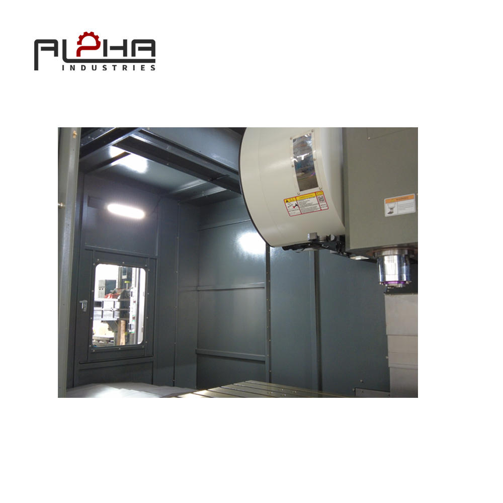


Large steel components are common in many industrial manufacturing applications. Machine frames, equipment housings, mounting plates, structural brackets, pump components, and other heavy mechanical parts may require milling, drilling, boring, tapping, and precision hole machining.
For Russian manufacturers, the ability to process these components efficiently is an important consideration when upgrading a machine shop or adding CNC machining capacity.
However, machining a large component is not simply a matter of placing it on a bigger machine table.
The workpiece must fit within the machine's working envelope. Its weight must remain within the permitted table capacity. The fixture must be installed without restricting tool movement. The spindle must reach the required machining positions, and the complete setup must remain stable throughout the operation.
A VMC that appears suitable according to its advertised table size may still be unsuitable for a particular component once fixtures, clamps, tool holders, and machining clearances are considered.
This is especially important when manufacturing large steel parts with multiple machined faces or complex hole patterns.
The challenge is to match the VMC configuration with the actual workpiece and production process.
A suitable machine selection should consider:
-
Maximum workpiece dimensions
-
Maximum table loading capacity
-
X, Y, and Z-axis travel
-
Fixture dimensions and height
-
Tool access and spindle clearance
-
Workpiece positioning requirements
-
Multi-side machining operations
-
Loading and unloading arrangements
-
Required dimensional accuracy
-
Future production flexibility
For manufacturers in Russia, careful evaluation of these factors can help avoid purchasing a machine that is technically operational but poorly matched to everyday production requirements.
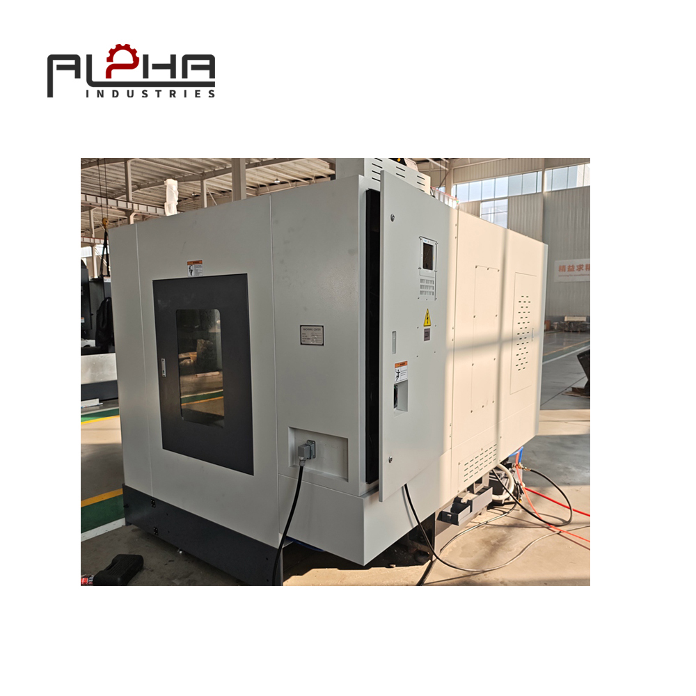
Understand the Challenges of Machining Large Steel Components
Large workpieces create different machining challenges from small, standardized components.
Their dimensions, weight, geometry, and handling requirements can influence almost every stage of the manufacturing process.
Large Dimensions Do Not Automatically Mean Large Machining Capacity
A workpiece may fit physically on the worktable but still be difficult to machine.
For example, a long steel plate may fit within the table dimensions, but the spindle may not reach every required position if the fixture or clamping arrangement occupies too much space.
Similarly, a component may fit within the X-axis and Y-axis travel but exceed the available Z-axis clearance after the fixture and workpiece are installed.
Therefore, manufacturers should evaluate the complete machining envelope rather than relying on worktable dimensions alone.
Heavy Workpieces Require Proper Support
Large steel components can place considerable loads on the machine table and fixture.
If the workpiece is not supported correctly, the setup may become unstable during machining.
The consequences may include:
-
Workpiece movement
-
Fixture deformation
-
Difficulty maintaining machining references
-
Reduced positioning repeatability
-
Additional setup adjustments
-
Increased loading and unloading time
The machine, worktable, fixture, and workpiece must be considered as one complete system.
Complex Geometry Can Limit Tool Access
Large components often include different machining surfaces, recessed areas, mounting holes, slots, and angled features.
Even if the workpiece fits on the machine, some areas may be difficult to reach with a standard tool arrangement.
The machining process should therefore be reviewed before machine selection.
Manufacturers should identify the most difficult machining positions and determine whether the proposed VMC can reach them with suitable tools and fixtures.
Repeated Repositioning Can Increase Production Time
When a component requires machining on several sides, operators may need to reposition it manually.
Every repositioning operation introduces additional work.
The process may require:
-
Removing the workpiece
-
Changing its orientation
-
Installing it again
-
Re-establishing the machining reference
-
Checking alignment
-
Running the next machining operation
For heavy components, these steps can require additional lifting equipment and coordination.
Reducing unnecessary repositioning is therefore an important objective when planning large-part machining.
Evaluate VMC Worktable Dimensions and Maximum Load Capacity
The worktable is one of the first specifications buyers should examine.
However, table dimensions and maximum load capacity must be considered separately.
Check the Actual Workpiece Footprint
Start by identifying the maximum length and width of the components that will be machined.
Then include the space required for the fixture and clamping devices.
The total setup footprint may be significantly larger than the workpiece itself.
A practical evaluation should include:
|
Evaluation Item |
What to Check |
|---|---|
|
Workpiece length |
Maximum component length |
|
Workpiece width |
Maximum component width |
|
Fixture footprint |
Space occupied by the fixture |
|
Clamping space |
Clearance for clamps and bolts |
|
Table dimensions |
Available worktable area |
|
Tool access |
Space required for spindle movement |
|
Loading access |
Space required for installation and removal |
A machine table should not be considered suitable simply because the workpiece dimensions are smaller than the table dimensions.
The complete setup must fit safely and allow the required machining movements.
Understand Maximum Table Load
The maximum table load indicates the load the machine table is designed to support under specified conditions.
Buyers should consider the combined weight of:
-
Workpiece
-
Fixture
-
Clamping devices
-
Positioning equipment
-
Other accessories installed on the table
The combined load must remain within the machine manufacturer's specified limit.
Manufacturers should also confirm any relevant restrictions regarding load distribution and workpiece positioning.
A concentrated load may create different mechanical conditions from a uniformly distributed load.
Consider the Workpiece Center of Gravity
Workpiece weight is not the only consideration.
The position of the center of gravity can affect how the component loads the fixture and worktable.
An irregular steel casting or large housing may have an uneven weight distribution.
The fixture should provide suitable support and prevent unstable positioning.
Where necessary, the loading arrangement should be reviewed with the machine supplier or a qualified fixture designer.
Plan for Future Workpiece Sizes
Machine selection should reflect both current and reasonably expected production requirements.
If a manufacturer frequently receives different component sizes, a machine with some additional working capacity may provide greater flexibility.
However, buying a machine that is unnecessarily large can increase investment and floor-space requirements.
The objective is to select a practical working range based on real production data.
Match X, Y, and Z-Axis Travel to the Actual Machining Process
Axis travel determines the available movement range of the machine.
For large steel components, all three axes must be evaluated together.
X-Axis Travel: Lengthwise Machining
The X-axis often determines how far the spindle can move along the length of the worktable.
For long steel plates, frames, and mounting components, sufficient X-axis travel is important.
However, the usable travel must be checked against:
-
Workpiece positioning
-
Fixture dimensions
-
Tool length
-
Spindle nose clearance
-
Machining reference points
The nominal X-axis travel alone does not guarantee that every point on a long workpiece can be machined.
Y-Axis Travel: Width and Side Access
Y-axis travel affects the machine's ability to reach different positions across the workpiece.
For wide components, insufficient Y-axis movement may restrict machining access.
The fixture and clamps may also reduce the usable area.
Buyers should check whether the spindle can reach all required positions without interference.
Z-Axis Travel: Workpiece Height and Tool Clearance
Z-axis travel is particularly important when machining tall components or using fixtures that raise the workpiece above the table.
The available vertical space must account for:
-
Fixture height
-
Workpiece height
-
Tool length
-
Tool holder length
-
Spindle nose position
-
Required approach and withdrawal movements
A workpiece may fit on the table but still be too tall for the required machining operation.
Evaluate the Complete Working Envelope
Before purchasing a VMC, manufacturers should provide representative workpiece drawings to the supplier.
The supplier can then help review whether the required machining positions are within the machine's usable working envelope.
This is more reliable than selecting equipment based on axis travel figures alone.
Design the Fixture Around the Workpiece, Not Just the Machine Table
Workholding is a critical part of large-component machining.
A suitable fixture should provide stable support, repeatable positioning, and sufficient tool access.
Use a Fixture That Matches the Component Geometry
Different components require different workholding arrangements.
Common solutions include:
-
T-slot clamping systems
-
Machine vises
-
Modular fixtures
-
Dedicated fixtures
-
Support blocks
-
Angle plates
-
Custom locating devices
For large irregular components, a dedicated or modular fixture may be more practical than a standard vise.
The fixture should support the component at suitable locations and provide enough clearance for machining.
Keep Clamping Devices Outside Critical Toolpaths
Clamps and bolts can obstruct tool movement.
This is particularly important when machining large parts with holes, pockets, slots, and multiple surfaces.
Before machining, operators should verify the complete toolpath and check for potential interference.
The fixture design should allow the spindle and cutting tool to reach the required machining positions safely.
Consider Workpiece Deformation
Large plates and thin-walled steel structures may deform during clamping.
Excessive clamping force can distort the workpiece and influence the final dimensions.
The fixture should provide enough holding force without creating unnecessary deformation.
For components with flexible sections, additional supports may be needed.
The support arrangement should be designed according to the workpiece geometry and machining forces.
Make Repeated Setup More Consistent
For manufacturers producing the same components regularly, standardized fixtures can help reduce setup variation.
A repeatable fixture arrangement can simplify:
-
Workpiece positioning
-
Reference setting
-
Clamping procedures
-
Toolpath verification
-
Production changeovers
-
Quality inspection
This is especially useful when different operators handle the same component type.
Reduce Repeated Setup Through Multi-Side Machining Planning
Large components may require machining on several faces.
Repeated repositioning can increase production time and make it harder to maintain consistent references.
A well-planned machining sequence can reduce unnecessary handling.
Identify All Required Machining Faces Before Production
Start by reviewing the engineering drawing.
Identify:
-
Top machining surfaces
-
Side machining surfaces
-
Mounting holes
-
Threaded holes
-
Slots
-
Pockets
-
Reference surfaces
-
Critical dimensional relationships
This helps determine how many setups are actually required.
Combine Operations Where Practical
If several operations can be completed in one setup, the manufacturer may reduce workpiece handling and repeated alignment.
For example, a steel mounting plate may require surface milling, drilling, and tapping.
If the machine configuration and tool access allow these operations to be completed in one setup, separate handling steps may be reduced.
However, this depends on the component geometry, machine capability, and fixture arrangement.
Consider Suitable Workholding Accessories
Depending on the machining requirements, manufacturers may consider:
-
Precision fixtures
-
Angle plates
-
Rotary tables
-
Indexing devices
-
Modular clamping systems
These accessories can expand workpiece positioning options.
However, they also occupy space and may reduce available axis clearance.
Their dimensions, weight, and compatibility must be checked before installation.
Understand When a Standard VMC Is Not Enough
Not every multi-side machining requirement can be solved by adding accessories to a standard vertical machining center.
Some components require access to multiple faces that cannot be reached efficiently with the available machine configuration.
In these situations, buyers may need to evaluate:
-
Horizontal machining centers
-
Four-axis machining centers
-
Five-axis machining centers
-
Gantry machining centers
-
Dedicated large-part milling equipment
The correct machine type depends on the required machining geometry and production volume.
The purpose is not to choose the most complex machine, but to select the simplest configuration that can reliably complete the required operations.
Plan Loading and Unloading for Heavy Steel Workpieces
Large-component machining involves more than cutting performance.
The process of moving a workpiece onto and off the machine can affect production efficiency and workshop safety.
Review Workshop Lifting Equipment
Before installing a VMC for large steel components, manufacturers should review the available lifting equipment.
Depending on the workpiece weight and workshop layout, loading may involve overhead cranes, hoists, forklifts, or other suitable material-handling equipment.
The lifting equipment must be appropriate for the actual load and comply with applicable safety requirements.
Check Machine Access and Workshop Layout
A large machine requires sufficient surrounding space.
The workshop layout should allow:
-
Workpiece transportation
-
Lifting equipment operation
-
Fixture installation
-
Operator access
-
Maintenance access
-
Chip removal
-
Finished-part unloading
A machine that fits inside the workshop may still be difficult to operate if there is insufficient space around it.
Standardize the Loading Process
Repeated production can benefit from a standardized loading procedure.
The process may define:
-
Workpiece inspection before lifting
-
Approved lifting points
-
Fixture preparation
-
Workpiece positioning
-
Clamping verification
-
Machining reference confirmation
-
Safe unloading after machining
The actual procedure should follow the workshop's risk assessment and equipment manufacturer's instructions.
Include Handling Time in Production Planning
Machining time is only one part of the total production cycle.
For large components, loading, unloading, cleaning, positioning, and inspection may account for a substantial part of the process.
Manufacturers should evaluate the complete production cycle rather than comparing machines only by cutting speed.
Choose the Right VMC Configuration for Different Large-Part Applications
Different workpieces require different machine configurations.
A machine suitable for a large mounting plate may not be the best solution for a tall equipment housing.
Large Steel Plates and Mounting Bases
Typical operations may include:
-
Surface milling
-
Drilling
-
Tapping
-
Slot milling
-
Pocket machining
Important VMC considerations include worktable dimensions, X-axis travel, fixture arrangement, and tool access.
Industrial Equipment Housings
Housings may include multiple mounting surfaces, bores, holes, and internal features.
Important considerations include:
-
Workpiece height
-
Z-axis clearance
-
Fixture design
-
Tool length
-
Machining sequence
-
Reference consistency
For complex housing geometries, buyers should verify whether a vertical machining center can reach the required surfaces without excessive repositioning.
Mechanical Frames and Structural Components
Large frames may have long dimensions and multiple mounting points.
Important considerations include:
-
Table size
-
Axis travel
-
Workpiece support
-
Clamping arrangement
-
Positioning accuracy
-
Loading access
For very long frames, a conventional VMC may not provide a suitable working envelope.
A gantry-type or other large-format machining solution may be more appropriate.
Pump and Valve Components
Pump and valve components may require accurate holes, sealing surfaces, slots, and mounting features.
The machine should be selected according to the largest workpiece, required tolerances, machining operations, and fixture arrangement.
The ability to maintain consistent references across different operations is particularly important.
Custom Steel Components
Job shops and manufacturers producing non-standard components may need greater flexibility.
A suitable VMC should accommodate a practical range of workpiece dimensions and fixture arrangements.
However, flexibility should not come at the expense of safe loading, adequate table capacity, or reliable machining access.
Consider Accuracy Requirements When Machining Large Components
Large workpieces can introduce additional dimensional control challenges.
A component may be machined in several operations, repositioned between setups, or supported at different locations.
These factors can influence dimensional consistency.
Establish a Reliable Workpiece Reference
A consistent reference system is important when machining several features on a large component.
Manufacturers should define the datum surfaces and reference positions before production.
The machining program, fixture, and inspection procedure should use compatible reference information.
Minimize Unnecessary Repositioning
Every additional setup creates another opportunity for alignment variation.
Where possible, critical related features should be machined within the same setup.
When repositioning is necessary, suitable locating and measurement procedures should be used.
Verify Critical Dimensions
Inspection requirements should be established before machining.
Depending on the component, important measurements may include:
-
Overall dimensions
-
Hole positions
-
Hole diameters
-
Parallelism
-
Flatness
-
Perpendicularity
-
Surface roughness
The inspection method should be appropriate for the drawing tolerances and component size.
Consider Thermal and Process Effects
Large steel components may experience dimensional changes due to temperature variation and machining heat.
The impact depends on material, geometry, machining conditions, and inspection environment.
For precision work, manufacturers should follow suitable temperature-control and measurement procedures.
What Should Russian Manufacturers Check Before Purchasing a VMC?
A reliable machine selection process should start with actual production requirements.
The following checklist can help buyers compare VMC configurations.
|
Selection Factor |
Key Questions |
|---|---|
|
Workpiece dimensions |
What are the maximum length, width, and height? |
|
Workpiece weight |
What is the heaviest complete setup? |
|
Worktable |
Are table dimensions and load capacity sufficient? |
|
X-axis travel |
Can the spindle reach all required positions? |
|
Y-axis travel |
Is there enough width for the machining process? |
|
Z-axis travel |
Is there sufficient clearance for the workpiece and fixture? |
|
Spindle |
Is the spindle suitable for the required materials and operations? |
|
Tool magazine |
Can it accommodate the necessary tools? |
|
Workholding |
Are standard or customized fixtures required? |
|
Machine layout |
Can the workshop load and unload the workpiece safely? |
|
Inspection |
Can the required dimensions be measured reliably? |
|
Technical support |
Are documentation, installation guidance, and service arrangements available? |
Provide Real Workpiece Drawings
A supplier can make a more accurate recommendation when the buyer provides representative engineering drawings.
Useful information includes:
-
Workpiece dimensions
-
Material grade
-
Workpiece weight
-
Required machining operations
-
Critical tolerances
-
Machined surface requirements
-
Expected production volume
-
Preferred fixture arrangement
This information helps identify whether a standard VMC is appropriate or whether a different machining center configuration should be considered.
Request a Practical Machining Assessment
Where possible, buyers should request a machining demonstration or technical assessment based on a representative workpiece.
The assessment should consider:
-
Workpiece positioning
-
Fixture dimensions
-
Table loading
-
Tool access
-
Machining sequence
-
Required accuracy
-
Loading and unloading
A practical assessment provides more useful information than comparing specification sheets without considering the actual component.
Common VMC Selection Mistakes When Machining Large Workpieces
Mistake 1: Selecting a Machine Only by Table Size
A large table does not automatically guarantee sufficient machining capacity.
Axis travel, spindle clearance, fixture dimensions, and tool access must also be considered.
Mistake 2: Ignoring Fixture Weight
The fixture contributes to the total table load.
Buyers should calculate the combined weight of the workpiece and all installed workholding equipment.
Mistake 3: Overlooking Z-Axis Clearance
Tall fixtures and large workpieces can reduce available vertical machining space.
The complete tool assembly must have sufficient clearance.
Mistake 4: Ignoring Workpiece Handling
A machine may have suitable cutting specifications but still create workflow difficulties if the workshop cannot load and unload components efficiently.
Mistake 5: Assuming Every Large Component Needs a Larger VMC
Some parts may be better suited to horizontal, gantry, or multi-axis machining centers.
The machine type should match the required machining access and component geometry.
Mistake 6: Buying Without Reviewing Actual Drawings
General specifications cannot replace a technical review of the actual workpiece.
Representative drawings help identify capacity limitations before purchasing.
Frequently Asked Questions About VMCs for Large Workpieces
What is the most important factor when choosing a VMC for large steel components?
The most important factor is the complete machining capacity of the machine. Buyers should evaluate worktable dimensions, maximum load, axis travel, fixture space, spindle clearance, and workpiece accessibility together.
How do I know whether a VMC can handle my workpiece weight?
Compare the combined weight of the workpiece, fixture, clamps, and accessories with the manufacturer's specified maximum table load. Also confirm any restrictions related to load distribution and workpiece positioning.
Is worktable size the same as machining range?
No. Worktable dimensions describe the physical table area, while machining range is determined by the machine's axis travel and usable clearance. Fixture dimensions and tool length also influence the accessible machining area.
What VMC axis travel is required for large components?
There is no universal travel requirement. The correct X, Y, and Z travel depends on workpiece dimensions, fixture height, tool length, machining positions, and required clearances. Buyers should assess representative workpiece drawings before selecting a machine.
Can a standard VMC machine large steel plates?
Yes, provided the plate dimensions, total setup weight, fixture arrangement, and machining positions are within the machine's specified capacity. The workpiece must also be supported and clamped appropriately.
Can a VMC machine all sides of a large component?
It depends on the machine configuration and workpiece geometry. Some operations can be completed using suitable fixtures or indexing accessories. Other applications may require a horizontal, four-axis, five-axis, or gantry machining center.
Why is Z-axis travel important for large workpieces?
Z-axis travel determines the available vertical movement of the spindle. Tall components, elevated fixtures, long tools, and tool holders all use part of the available clearance.
How can manufacturers reduce repeated setup for large parts?
They can review the machining sequence, combine operations where practical, use suitable fixtures, establish consistent workpiece references, and consider appropriate positioning accessories. The machine must still provide safe access to all required machining positions.
Should I choose a larger VMC for future production needs?
A machine with additional capacity may offer flexibility when future workpiece sizes are reasonably predictable. However, an unnecessarily large machine can increase investment and workshop-space requirements. Selection should be based on current production data and realistic future requirements.
What information should I send a supplier when requesting a VMC quotation?
Provide workpiece drawings, maximum dimensions, material, weight, required machining operations, critical tolerances, expected production volume, and any preferred workholding arrangements. This allows the supplier to evaluate machine capacity more accurately.
Conclusion: Match VMC Capacity to Real Production Requirements
For Russian manufacturers working with large steel components, selecting a suitable vertical machining center requires more than checking the machine's advertised worktable dimensions.
The complete machining process must be considered, including workpiece size, total setup weight, axis travel, fixture arrangement, tool access, multi-side machining, and workshop handling.
A machine with insufficient working clearance or table capacity can create unnecessary setup difficulties, limit machining flexibility, and increase production time.
On the other hand, a correctly selected VMC can help manufacturers organize machining operations more effectively and handle a wider range of industrial components within the machine's intended working envelope.
Before purchasing, manufacturers should prepare representative workpiece drawings and evaluate the complete setup with the equipment supplier.
ALPHA provides metalworking machinery solutions for industrial manufacturing applications. If your company in Russia is planning to machine large steel plates, equipment housings, mounting bases, or other mechanical components, our team can help discuss the required VMC working range, worktable capacity, spindle configuration, and machining applications.
Contact ALPHA to discuss your workpiece dimensions and production requirements.
Contact Us: https://alpha-cnc.com/contact-us