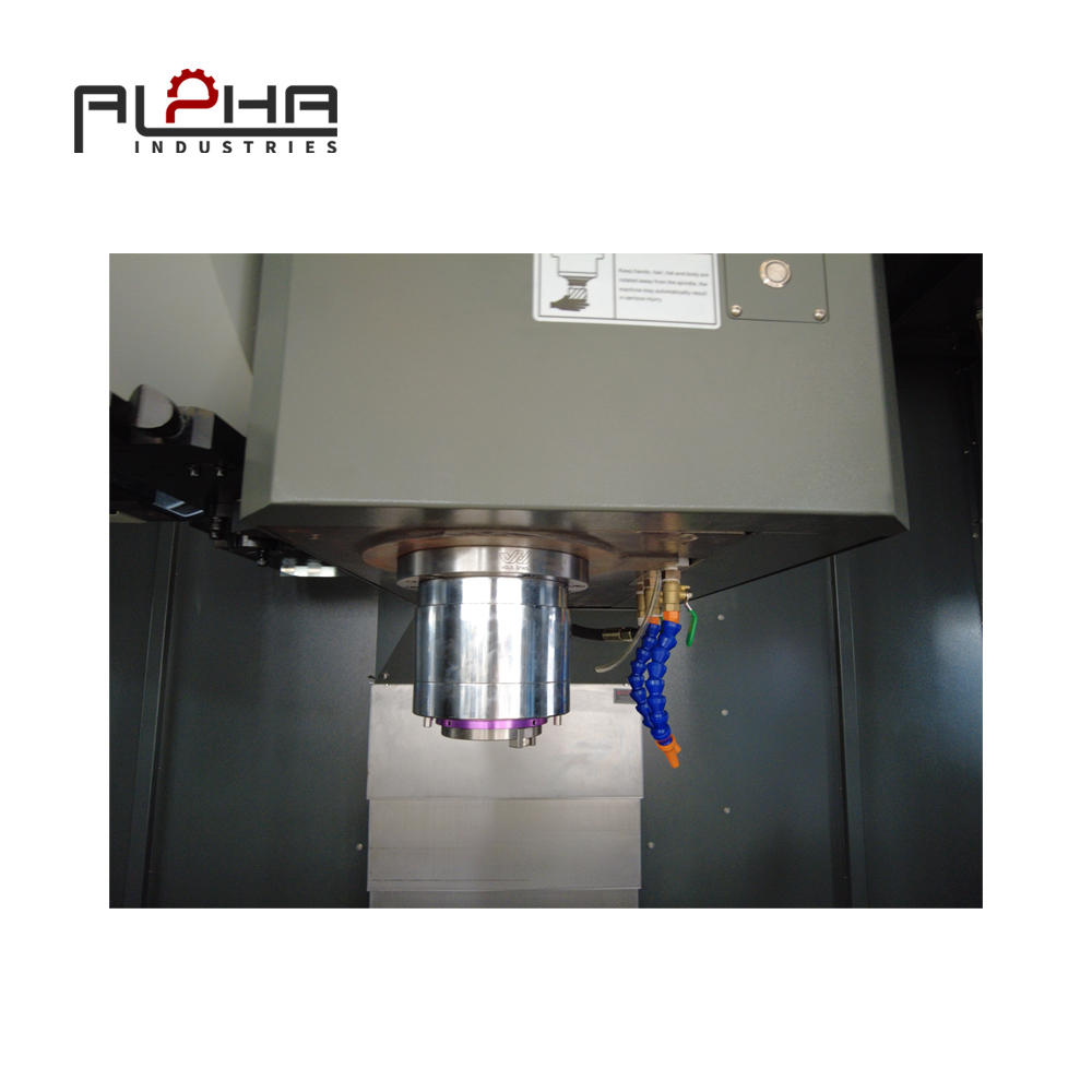


Why VMC Chatter Control Matters in Steel Machining
Steel machining places considerable demands on a vertical machining center. Depending on the material grade, workpiece geometry, cutting tool, and machining operation, the machine must maintain stable cutting conditions while removing material efficiently.
For Russian manufacturers producing industrial machinery, mechanical components, equipment housings, brackets, plates, and other steel parts, machining stability is an important factor in production quality.
One problem that can affect this stability is chatter.
Chatter is a form of self-excited vibration that develops during machining. It can occur when the interaction between the cutting tool, workpiece, spindle, and machine structure becomes unstable.
Unlike normal cutting noise, chatter often produces repetitive vibration patterns, visible marks on the machined surface, and irregular cutting behavior.
The consequences can include:
-
Visible vibration marks on machined surfaces.
-
Poor surface roughness.
-
Accelerated cutting tool wear.
-
Reduced tool life.
-
Dimensional deviations.
-
Increased machining time.
-
Additional finishing operations.
-
Unexpected tool or workpiece damage.
For manufacturers working with steel components, these problems can affect both production efficiency and product quality.
The solution is not simply to reduce spindle speed or use a stronger cutting tool. Chatter control requires a systematic understanding of the complete machining process.
A stable VMC machining process depends on several connected factors:
-
Machine structural rigidity.
-
Workpiece clamping stability.
-
Cutting tool and tool holder selection.
-
Spindle speed and feed rate.
-
Axial and radial depth of cut.
-
Toolpath strategy.
-
Coolant and chip evacuation.
-
Machining inspection and process verification.
Understanding these factors can help Russian manufacturers improve steel machining stability and achieve more consistent results from their vertical machining centers.
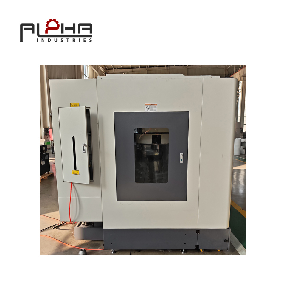
Understand What Causes Chatter During VMC Steel Milling
Before adjusting cutting parameters, manufacturers should identify why vibration occurs.
Chatter is not necessarily caused by one individual component. It often results from the interaction of several mechanical and cutting conditions.
Insufficient Machine Rigidity
The machine structure must resist the forces generated during cutting.
When milling steel, cutting forces depend on material properties, cutter geometry, cutting depth, feed rate, and other machining conditions.
If the machine structure does not provide sufficient rigidity for the operation, vibration may develop.
Important structural elements include:
-
Machine bed.
-
Column.
-
Spindle housing.
-
Worktable.
-
Guideways.
-
Spindle support structure.
-
Axis drive system.
The machine's structural design influences how effectively it can resist cutting forces.
A VMC intended for heavier steel milling should therefore be evaluated not only by its spindle power but also by its overall structural configuration.
Unstable Workpiece Clamping
A rigid machine cannot compensate for a poorly secured workpiece.
If a steel component moves or vibrates under cutting forces, chatter may appear even when the spindle and cutting tool are operating correctly.
This is particularly important when machining:
-
Thin steel plates.
-
Long workpieces.
-
Components with irregular shapes.
-
Parts with limited clamping surfaces.
-
Workpieces with large unsupported sections.
The clamping arrangement should provide adequate support close to the machining area without interfering with tool movement.
Excessive Tool Overhang
Tool overhang refers to the length of the cutting tool extending from the holder.
A longer tool assembly is generally more susceptible to bending and vibration.
When machining deep pockets or hard-to-reach surfaces, operators may need longer tools. However, excessive overhang can reduce cutting stability.
Manufacturers should use the shortest practical tool assembly that provides sufficient machining access.
Incorrect Cutting Parameters
Spindle speed, feed rate, and depth of cut influence the cutting forces and vibration behavior.
An unsuitable combination can create unstable cutting conditions.
For example, increasing the depth of cut may improve material removal in some situations, but it can also increase cutting forces beyond what the tool, fixture, or machine can handle.
Similarly, an unsuitable spindle speed may place the machining process within an unstable vibration range.
The correct parameters must be selected according to the complete machining system.
Select a VMC with Suitable Structural Rigidity for Steel Machining
Machine rigidity is one of the foundations of stable machining.
When selecting a vertical machining center for steel components, buyers should evaluate the machine structure rather than relying only on general descriptions such as heavy-duty or high-precision.
Examine the Machine Bed and Column
The machine bed and column form the main supporting structure.
Their design influences how cutting forces are transferred through the machine.
Important considerations include:
-
Structural configuration.
-
Casting material.
-
Casting design.
-
Rib arrangement.
-
Machine weight.
-
Column support.
-
Guideway arrangement.
Many conventional VMCs use cast iron structures because cast iron offers useful rigidity and vibration-damping characteristics.
However, the actual performance depends on the casting design, manufacturing quality, machine geometry, and assembly accuracy.
Buyers should request technical information about the machine structure and evaluate whether it is appropriate for their typical steel machining operations.
Consider the Guideway Configuration
Linear guideways support the movement of the machine axes.
Different guideway configurations offer different characteristics.
Roller-type linear guides generally provide a larger contact area and high load-carrying capability, while ball-type linear guides can provide smooth movement and are commonly used in various machining applications.
The appropriate configuration depends on the machine design and intended cutting conditions.
Buyers should evaluate:
-
Guideway type.
-
Guideway size.
-
Load capacity.
-
Axis arrangement.
-
Machine rigidity.
-
Positioning requirements.
The objective is to select a machine with a suitable balance of movement performance and structural support.
Evaluate Spindle Rigidity and Bearing Arrangement
The spindle is directly connected to the cutting tool and plays a central role in machining stability.
A spindle assembly must support the cutting tool while maintaining suitable rotational accuracy and rigidity.
Buyers should consider:
-
Spindle type.
-
Spindle taper.
-
Maximum speed.
-
Torque characteristics.
-
Bearing configuration.
-
Cooling method.
-
Tool interface.
-
Recommended machining applications.
A high spindle speed does not automatically mean the machine is suitable for heavy steel milling.
For steel applications, buyers should pay particular attention to available torque and the spindle's performance across the intended cutting-speed range.
Do Not Judge Rigidity by Machine Weight Alone
Machine weight can provide useful information, but it is not a complete measure of machining rigidity.
Two machines with similar weights may have different structural designs and dynamic behavior.
A proper evaluation should consider the complete machine structure, spindle system, axis configuration, and machining test results.
Where possible, buyers should request a cutting demonstration using workpieces and tools similar to their actual production requirements.
Improve Workpiece Clamping to Prevent Vibration
Workholding is one of the most important areas to check when chatter occurs.
Even a well-designed VMC can produce unstable machining results if the workpiece is not properly supported.
Use a Suitable Fixture for the Workpiece Geometry
Different workpieces require different clamping methods.
A standard machine vise may be suitable for rectangular components, while irregular steel parts may require customized fixtures.
Possible workholding solutions include:
-
Machine vises.
-
T-slot clamping kits.
-
Modular fixtures.
-
Dedicated fixtures.
-
Angle plates.
-
Support blocks.
-
Custom clamping devices.
The selected fixture should resist cutting forces while providing sufficient access for the cutting tool.
Minimize Unsupported Workpiece Areas
Long or thin steel components can deflect under cutting forces.
If the workpiece is supported only at a few points, unsupported sections may vibrate during machining.
Where practical, additional supports can be positioned close to the machining area.
However, support placement must be planned carefully.
Incorrect support positioning can distort the workpiece during clamping and cause dimensional changes after machining.
Avoid Excessive Clamping Force
Increasing clamping force does not always improve machining stability.
Excessive force can deform thin or flexible components.
After the workpiece is released, the deformation may disappear, resulting in dimensional deviations.
The clamping method should provide sufficient holding force without unnecessarily distorting the component.
Verify Clamping Before Cutting
Before starting the machining program, operators should check:
-
Workpiece contact with locating surfaces.
-
Fixture stability.
-
Clamping force.
-
Support positioning.
-
Tool access.
-
Potential collision points.
-
Workpiece movement under expected cutting conditions.
For repeated production, a standardized fixture arrangement can help maintain consistency between machining batches.
Choose the Right Cutting Tool and Tool Holder
The cutting tool is another important factor in chatter control.
A suitable tool should match the material, machining operation, required surface quality, and machine capability.
Select an Appropriate Cutter Geometry
Different cutter geometries produce different cutting forces and chip characteristics.
When selecting an end mill for steel machining, manufacturers should consider:
-
Cutter diameter.
-
Number of cutting edges.
-
Helix angle.
-
Rake angle.
-
Cutting edge geometry.
-
Tool substrate.
-
Coating.
-
Recommended cutting conditions.
The appropriate geometry depends on the steel grade and machining operation.
A tool designed for roughing may not provide the same surface finish as a finishing cutter.
Likewise, a finishing tool should not automatically be used for aggressive material removal.
Reduce Tool Overhang
One of the simplest ways to improve tool stability is to minimize unnecessary overhang.
A shorter tool assembly generally provides greater resistance to bending.
When planning deep machining operations, consider whether the required depth can be achieved using:
-
A different tool diameter.
-
A shorter tool holder.
-
A revised workpiece orientation.
-
An alternative machining sequence.
-
A suitable extension system.
Long-reach tools may still be necessary for certain components, but their cutting conditions should be selected carefully.
Choose a Suitable Tool Holder
The tool holder connects the cutting tool to the spindle.
Its clamping performance, balance, and rigidity can influence machining stability.
Common tool holder considerations include:
-
Tool interface compatibility.
-
Clamping method.
-
Tool diameter range.
-
Balance quality.
-
Holder rigidity.
-
Maximum operating speed.
-
Tool runout.
The holder must be compatible with the machine spindle and the selected cutting tool.
Poor tool holding or excessive runout can create uneven cutting loads and accelerate tool wear.
Monitor Tool Wear
A worn cutting edge may generate higher cutting forces and unstable chip formation.
This can increase vibration and reduce surface quality.
Operators should inspect tools according to the machining conditions and the manufacturer's recommendations.
Warning signs may include:
-
Unusual cutting noise.
-
Increased spindle load.
-
Visible edge damage.
-
Irregular chip formation.
-
Surface finish deterioration.
-
Dimensional changes.
Replacing a worn tool at an appropriate time can help prevent additional machining problems.
Optimize Spindle Speed to Avoid Unstable Cutting Conditions
Spindle speed has a significant influence on chatter behavior.
In certain machining conditions, changing the spindle speed can move the process away from an unstable vibration range.
This is why reducing chatter does not always mean reducing spindle speed.
Understand the Relationship Between Speed and Chatter
During milling, the cutting edges repeatedly engage and disengage with the workpiece.
This creates periodic cutting forces.
If the interaction between these forces and the machine-tool-workpiece system becomes unstable, chatter may develop.
The vibration behavior depends on factors such as:
-
Spindle speed.
-
Number of cutting edges.
-
Tool geometry.
-
Tool overhang.
-
Workpiece rigidity.
-
Machine dynamic characteristics.
-
Cutting depth.
A small change in spindle speed can sometimes improve cutting stability.
However, the correct speed should be established through controlled testing rather than random adjustments.
Use a Controlled Speed Adjustment Method
When chatter occurs, manufacturers can investigate the spindle speed systematically.
A practical approach is:
-
Record the current spindle speed.
-
Record the cutting tool and holder configuration.
-
Check workpiece clamping.
-
Reduce the cutting load if necessary.
-
Adjust spindle speed within the tool manufacturer's recommended range.
-
Perform a controlled test cut.
-
Inspect the machined surface and cutting behavior.
-
Record the results.
Changing one parameter at a time makes it easier to identify the reason for improvement.
Avoid Using Maximum Spindle Speed as a Default
A VMC's maximum spindle speed is a machine capability, not a recommended setting for every machining operation.
Steel milling often requires careful consideration of cutting speed, tool diameter, material properties, and tool geometry.
Using an excessively high spindle speed may increase heat generation or tool wear without providing a meaningful productivity benefit.
The correct spindle speed should support stable material removal and acceptable tool life.
Balance Feed Rate and Depth of Cut for Stable Steel Milling
Feed rate and depth of cut influence cutting forces and material removal rate.
An appropriate combination can improve machining efficiency while maintaining stable cutting conditions.
Understand Feed per Tooth
For milling operations, feed per tooth is an important parameter.
It describes the amount of material advanced for each cutting edge during one tooth engagement.
An unsuitable feed per tooth can affect:
-
Chip thickness.
-
Cutting forces.
-
Tool loading.
-
Surface finish.
-
Tool wear.
If the feed is too low, the cutting edge may rub rather than remove material effectively under certain conditions.
If the feed is too high, the cutting forces may become excessive.
The correct value depends on the tool manufacturer's recommendations and the machining application.
Adjust Axial Depth of Cut
Axial depth of cut describes how much of the cutting edge is engaged along the tool axis.
Increasing axial engagement can increase cutting forces.
For long-reach tools or less rigid setups, a smaller axial depth may improve stability.
However, the best setting depends on the tool geometry and the operation.
Adjust Radial Engagement
Radial engagement describes how much of the cutter diameter is involved in cutting.
High radial engagement can produce substantial cutting forces.
Some modern milling strategies use smaller radial engagement with larger axial depth, depending on the tool design and machine capability.
These approaches can help control cutting forces in suitable applications.
However, the machining strategy must be selected according to the cutter manufacturer's guidance and the actual machine setup.
Avoid Changing Multiple Parameters Simultaneously
When chatter appears, changing spindle speed, feed rate, axial depth, radial engagement, and tool geometry at the same time makes troubleshooting difficult.
A better approach is to inspect the mechanical setup first and then adjust cutting parameters systematically.
This makes it easier to determine which change produces the greatest improvement.
Use Suitable Toolpath Strategies for Stable Steel Machining
The CNC toolpath determines how the cutting tool engages with the workpiece.
A suitable toolpath can reduce sudden changes in cutting load and improve machining stability.
Avoid Sudden Changes in Cutting Engagement
Sudden increases in tool engagement may produce high cutting forces.
This can happen when a cutter enters a deep pocket, encounters a corner, or engages a large amount of material unexpectedly.
A suitable CAM strategy should consider:
-
Tool entry direction.
-
Cutting engagement.
-
Corner geometry.
-
Step-over.
-
Axial depth.
-
Tool withdrawal.
-
Chip evacuation.
Smooth engagement can help reduce sudden load changes.
Consider Adaptive Milling Strategies
Adaptive milling is a machining approach designed to maintain more consistent tool engagement under suitable conditions.
Depending on the tool and CAM system, it can help distribute cutting forces more evenly.
Potential advantages include:
-
More consistent cutting engagement.
-
Reduced sudden load changes.
-
Improved material removal planning.
-
Better use of suitable cutting tools.
However, adaptive milling is not automatically suitable for every machine or workpiece.
The strategy should be validated against spindle power, tool specifications, workholding rigidity, and the machine's dynamic performance.
Plan Pocket Milling Carefully
Deep pockets can be challenging because the tool may have limited space for chip evacuation and may require a longer reach.
Manufacturers should consider:
-
Pocket depth.
-
Tool diameter.
-
Tool length.
-
Corner radius.
-
Material removal sequence.
-
Chip evacuation.
-
Tool entry method.
A suitable roughing strategy can reduce unnecessary tool loading.
Finishing operations should then be planned to achieve the required dimensional accuracy and surface quality.
Use Separate Roughing and Finishing Strategies
Roughing and finishing have different objectives.
Roughing removes most of the material, while finishing produces the final dimensions and surface condition.
Using separate tools and machining strategies can help prevent excessive finishing loads.
A suitable process may include:
-
Rough milling.
-
Semi-finishing.
-
Final finishing.
-
Dimensional inspection.
The exact sequence depends on the workpiece geometry, material, and required tolerance.
Manage Coolant and Chip Evacuation During Steel Machining
Coolant and chip management can influence machining stability.
Poor chip evacuation may cause chips to accumulate around the cutting tool or become trapped in the machining area.
This can lead to repeated cutting, tool damage, surface defects, or unstable machining conditions.
Ensure Effective Chip Removal
Steel machining can generate long or irregular chips depending on the material and cutting conditions.
The machining process should provide sufficient space and a suitable method for chip evacuation.
Important considerations include:
-
Coolant direction.
-
Nozzle positioning.
-
Coolant flow.
-
Tool geometry.
-
Chip formation.
-
Chip conveyor configuration.
-
Pocket depth.
For deep pockets, chip removal deserves particular attention.
If chips remain in the cutting area, the tool may recut them and experience additional cutting loads.
Select a Suitable Coolant Arrangement
The coolant system should match the machining process.
Buyers should consider:
-
Coolant pump capacity.
-
Coolant delivery method.
-
Nozzle arrangement.
-
Filtration requirements.
-
Coolant concentration.
-
Maintenance accessibility.
The correct coolant arrangement depends on the material, cutting tool, and machining operation.
Reducing coolant flow simply to save operating costs may cause excessive heat, poor chip evacuation, or tool wear.
Maintain Coolant Quality
Coolant condition should be checked according to the supplier's recommendations.
Contamination and incorrect concentration may affect cooling performance and machining stability.
Regular inspection helps maintain consistent machining conditions.
Measure Surface Quality and Verify the Machining Process
A machining process should not be judged by cutting noise alone.
Surface quality, dimensional accuracy, and tool condition provide useful information about process stability.
Inspect the Machined Surface
Chatter often produces repetitive marks on the machined surface.
Operators should inspect the workpiece after important machining operations.
The inspection may include:
-
Visual surface inspection.
-
Surface roughness measurement.
-
Dimensional measurement.
-
Geometric tolerance checks.
-
Tool wear inspection.
The appropriate method depends on the drawing requirements.
Use Surface Roughness Measurements Where Required
Surface roughness is an important quality indicator for many machined components.
Parameters such as Ra and Rz may be specified on engineering drawings.
The required surface finish depends on the component's function and application.
A visual inspection alone cannot replace a suitable roughness measurement when a numerical surface requirement is specified.
Compare Machining Results Across Different Parameters
When testing a new cutting strategy, record the results.
A useful machining test record may include:
| Test Information | Purpose |
|---|---|
| Workpiece material | Identifies machining conditions |
| Tool model | Records cutting tool configuration |
| Tool holder | Records tool assembly |
| Spindle speed | Identifies rotational speed |
| Feed rate | Records machining feed |
| Axial depth | Records cutting engagement |
| Radial engagement | Records cutter engagement |
| Machining time | Measures production performance |
| Surface condition | Evaluates chatter and finish |
| Tool condition | Checks wear and edge damage |
This information helps manufacturers build a more repeatable machining process.
Avoid Optimizing Surface Finish at the Expense of Production Stability
A very low feed rate or excessively conservative cutting strategy may improve the appearance of a particular surface but increase machining time unnecessarily.
The objective should be to balance:
-
Surface quality.
-
Dimensional accuracy.
-
Tool life.
-
Cutting stability.
-
Production time.
-
Total machining cost.
A good VMC machining process should meet the required quality standard while maintaining reliable production performance.
What Should Russian Manufacturers Check When Buying a VMC for Steel Machining?
Selecting a VMC for steel components requires more than comparing spindle speed and axis travel.
Buyers should consider whether the complete machine configuration can support their actual cutting requirements.
Machine Structure
Check the bed and column design, structural configuration, casting quality, guideway arrangement, and overall machine rigidity.
Ask the supplier which machine configuration is recommended for the intended steel machining applications.
Spindle Performance
Confirm:
-
Spindle type.
-
Spindle speed range.
-
Torque characteristics.
-
Spindle motor power.
-
Tool interface.
-
Cooling method.
-
Recommended applications.
Do not evaluate spindle performance using maximum RPM alone.
Axis Travel and Worktable Capacity
Check whether the machine can accommodate the actual workpiece and fixture arrangement.
Relevant specifications include:
-
X-axis travel.
-
Y-axis travel.
-
Z-axis travel.
-
Worktable dimensions.
-
Maximum workpiece weight.
-
Maximum workpiece height.
The fixture and tool assembly should also be considered when evaluating machining clearance.
Tool Magazine and Tool Compatibility
For multi-operation steel machining, buyers should confirm:
-
ATC type.
-
Tool capacity.
-
Maximum tool diameter.
-
Maximum tool length.
-
Maximum tool weight.
-
Tool interface.
-
Tool change requirements.
The selected tool magazine should match the workshop's production needs.
Request a Representative Machining Test
Where possible, provide the supplier with representative workpiece drawings or sample materials.
A practical machining demonstration can help evaluate:
-
Cutting stability.
-
Spindle performance.
-
Surface finish.
-
Tool changing.
-
Workpiece clamping.
-
Machining accuracy.
-
Chip evacuation.
The test conditions should be agreed upon in advance.
For a meaningful comparison, use similar materials, tools, cutting conditions, and inspection methods.
A Practical Chatter Troubleshooting Checklist for VMC Operators
When vibration appears during steel milling, operators should investigate the process systematically.
Machine and Spindle
-
Check machine installation and foundation conditions.
-
Inspect spindle condition according to the maintenance procedure.
-
Verify tool holder compatibility.
-
Check tool runout where appropriate.
-
Review spindle operating conditions.
Workpiece and Fixture
-
Confirm that the workpiece is properly clamped.
-
Check fixture rigidity.
-
Reduce unsupported workpiece areas.
-
Inspect locating surfaces.
-
Verify that the fixture is not interfering with the cutting tool.
Cutting Tool
-
Inspect cutting edges for wear or damage.
-
Check tool overhang.
-
Verify tool holder condition.
-
Confirm cutter suitability for the material.
-
Review tool manufacturer's cutting recommendations.
Cutting Parameters
-
Record spindle speed.
-
Check feed rate.
-
Review axial depth of cut.
-
Review radial engagement.
-
Adjust parameters systematically.
CNC Program and Toolpath
-
Check tool entry and exit movements.
-
Review sudden changes in cutting engagement.
-
Inspect deep pocket machining strategies.
-
Confirm the toolpath is suitable for the selected cutter.
-
Review chip evacuation movements.
Machining Quality
-
Inspect the surface for repetitive vibration marks.
-
Measure surface roughness where required.
-
Check critical dimensions.
-
Record tool condition.
-
Compare machining results after each adjustment.
If vibration continues after basic checks, the machine, spindle, tool holder, fixture, and machining process may require further technical inspection.
Operators should follow the machine manufacturer's safety and maintenance instructions and should not continue machining under conditions that risk damage or unsafe operation.
Frequently Asked Questions About VMC Chatter and Steel Machining
What causes chatter in a VMC?
Chatter is generally associated with unstable interaction between the cutting tool, workpiece, spindle, and machine structure. Common contributing factors include insufficient rigidity, poor workpiece clamping, excessive tool overhang, unsuitable cutting parameters, and unstable tool engagement.
How can I reduce vibration when milling steel on a VMC?
Start by checking workpiece clamping, tool overhang, tool holder condition, and machine setup. Then review spindle speed, feed rate, and cutting depth. Adjust one parameter at a time and verify the result through surface inspection and controlled machining tests.
Does reducing spindle speed always eliminate chatter?
No. Chatter depends on the dynamic behavior of the complete machining system. In some cases, increasing spindle speed within the permitted cutting range may improve stability. The correct speed should be determined through controlled testing and tool manufacturer recommendations.
Why does a VMC produce vibration marks on a steel workpiece?
Vibration marks may indicate chatter or unstable cutting conditions. Possible causes include poor clamping, excessive tool overhang, worn tools, unsuitable cutting parameters, or insufficient machine rigidity. The exact cause should be identified before changing the machining process.
Can a heavier VMC reduce chatter?
A machine with a rigid structure and suitable damping characteristics can help improve machining stability. However, machine weight alone does not determine chatter resistance. Buyers should evaluate structural design, spindle performance, guideways, machine configuration, and representative cutting test results.
How does tool overhang affect machining stability?
Longer tool overhang generally increases the tool assembly's susceptibility to bending and vibration. Using the shortest practical tool assembly can help improve rigidity, particularly during steel milling and deep-pocket machining.
Which cutting parameters are important for chatter control?
Important parameters include spindle speed, feed rate, feed per tooth, axial depth of cut, and radial engagement. Their appropriate values depend on the workpiece material, tool geometry, machine capability, and machining operation.
Does workpiece clamping affect VMC surface finish?
Yes. Poor workpiece support can allow the component to move or vibrate under cutting forces. A suitable fixture and correct clamping arrangement help maintain stability and improve machining consistency.
Is chatter more likely during roughing or finishing?
Chatter can occur during both operations. Roughing may involve higher cutting forces, while finishing can be sensitive to small vibrations that affect surface quality. The machining strategy should be appropriate for each operation.
What should I check before buying a VMC for steel machining?
Evaluate machine rigidity, spindle torque, spindle speed range, axis travel, worktable capacity, guideways, tool magazine, workholding requirements, and technical support. Where possible, request a representative cutting test using your actual workpiece material and machining requirements.
Conclusion: Achieve More Stable Steel Machining with the Right VMC Configuration
For Russian manufacturers producing steel components, machining stability is essential for maintaining consistent surface quality, dimensional accuracy, and production efficiency.
Chatter should not be treated as a problem that can always be solved by changing spindle speed or replacing the cutting tool.
It is influenced by the entire machining system, including the VMC structure, spindle, fixture, workpiece, tool holder, cutting parameters, and CNC toolpath.
A systematic approach can help manufacturers identify the main cause of vibration and make appropriate improvements.
When selecting a vertical machining center, buyers should evaluate machine rigidity, spindle performance, guideway configuration, worktable capacity, and the machine's suitability for their actual steel machining operations.
A suitable VMC, combined with correct workholding, appropriate tooling, and a verified machining strategy, can help establish a more stable and repeatable production process.
ALPHA provides metalworking machinery solutions for industrial manufacturing applications. If your company in Russia is looking for a VMC for steel milling, machinery components, or other precision machining applications, our team can discuss your workpiece dimensions, material requirements, cutting operations, spindle specifications, and production targets.
Contact ALPHA to discuss your VMC requirements and find a suitable CNC machining solution.
Contact Us: https://alpha-cnc.com/contact-us