

Why Accurate Flat Patterns Matter Before Bending Begins
A finished sheet metal component may appear simple, but producing it accurately requires more than cutting a sheet to the dimensions shown in a drawing. Before bending starts, the manufacturer must determine the correct flat pattern: the developed dimensions of the material before it is formed into its final shape.
If the flat pattern is incorrect, even a well-maintained press brake operated by an experienced technician may produce a part that does not meet its drawing dimensions.
A flange may be too long or too short. Hole positions may shift relative to a bend line. Two panels intended to fit together may leave an unexpected gap. A component may require additional trimming, rework, or a revised production drawing before it can be assembled.
These problems can be especially frustrating because the root cause may originate during engineering preparation rather than during the bending operation itself.
For Ukrainian sheet metal manufacturers producing industrial enclosures, machine covers, brackets, frames, electrical cabinets, agricultural equipment components, and customized metal parts, the connection between design and fabrication is important.
Production teams may need to switch between different materials, thicknesses, geometries, and customer drawings. A flat pattern that works for one material or tooling configuration may not deliver the same results under different conditions.
The key is to treat flat pattern development as part of the complete press brake process.
Design calculations, material specifications, tooling geometry, bending method, CNC programming, and first-piece inspection should work together. When these elements are coordinated, manufacturers can establish a more reliable path from the original CAD model to the finished component.
Why Flat Pattern Accuracy Is a Practical Challenge for Ukrainian Manufacturers
Many fabrication workshops handle a combination of repeat orders and customized work. One production batch may involve straightforward brackets, while another requires multi-bend panels, complex enclosures, or components with closely controlled assembly dimensions.
Each new design creates engineering requirements before material reaches the press brake.
The flat pattern must account for the way the sheet deforms during bending. The amount of material consumed by the bend depends on factors such as material thickness, inside bend radius, bend angle, material properties, and the actual forming process.
If the engineering calculation does not reflect the intended production conditions, the resulting blank dimensions may be unsuitable.
Customized Orders Increase Engineering Work
When a manufacturer produces many different components, it may not have a single standard flat pattern rule that works for every application.
Different products can use different materials, thicknesses, bend angles, and tooling configurations. A calculation developed for one part family may not be appropriate for another.
For Ukrainian job shops and contract manufacturers, this makes process documentation important. A repeatable approach helps engineering and production teams understand which assumptions were used for a particular component and whether those assumptions remain valid when the order returns.
Design Revisions Can Affect the Entire Production Process
A small change to a flange length, bend angle, material thickness, or inside radius can affect the flat pattern.
If the drawing is updated but the flat pattern or CNC bending program is not updated accordingly, production may continue using outdated information.
The result can be dimensional inconsistency between batches or a mismatch between the manufactured part and the latest customer drawing.
A controlled revision process helps prevent this problem by ensuring that design, cutting, bending, and inspection teams work from the correct approved information.
Material and Process Differences Can Change the Result
A flat pattern is not simply a geometric outline calculated independently of manufacturing.
The bend allowance used in the calculation must reflect the material and forming process as closely as practical. Changes in material grade, thickness, inside radius, tooling, and bending method may affect the final result.
This means that an engineering model should be validated against actual production conditions rather than treated as universally correct for every machine and material combination.
What Is Bend Allowance in Press Brake Manufacturing?
Bend allowance is the length of the material along the neutral axis within the bend region. It represents the portion of the flat sheet required to form the curved section of a bent component.
During bending, the material on the outside of the bend stretches while the material on the inside compresses. Between these regions lies the neutral axis, where longitudinal strain is approximately zero under the simplified model used for flat pattern calculations.
The location of the neutral axis depends on the material and bending conditions. The K-factor is commonly used to represent its position relative to the material thickness.
Bend allowance is important because the finished dimensions of a bent part cannot usually be obtained by simply adding the outside dimensions of all flanges and ignoring the material consumed by the bend.
The bend region must be accounted for in the flat pattern.
A Simplified Bend Allowance Formula
For a bend described by an inside radius and a bend angle measured as the change in direction of the sheet, a common theoretical formula is:
[
BA = \theta(R + KT)
]
Where:
-
BA = bend allowance
-
(\theta) = bend angle in radians
-
R = inside bend radius
-
K = K-factor
-
T = material thickness
The formula provides a useful basis for understanding how the bend region contributes to the developed length.
However, the result depends on the assumptions used for the material and bending process. The formula alone does not guarantee that a manufactured part will meet its drawing dimensions.
For production work, manufacturers should use the calculation method appropriate to their CAD software, material data, and bending process, then validate the result using representative parts.
Why the Bend Angle Convention Matters
Engineering software and manufacturing references may describe angles differently. Some calculations use the included angle of the finished part, while others use the amount of rotation from the original flat position.
These are not always the same value.
For example, a finished corner described as a 90-degree included angle typically corresponds to a 90-degree change in direction from the original flat sheet. For other geometries, the relationship may require more careful interpretation.
Before applying a bend allowance formula, confirm the angle convention used by the CAD system, calculation method, and production documentation.
A correct formula applied to the wrong angle definition can still produce an incorrect flat pattern.
Understanding the K-Factor in Sheet Metal Bending
The K-factor describes the position of the neutral axis relative to the material thickness.
In a simplified model, it is defined as the distance from the inside surface to the neutral axis divided by the material thickness.
[
K = \frac{t_n}{T}
]
Where:
-
(t_n) = distance from the inside surface to the neutral axis
-
T = material thickness
The K-factor is used in bend allowance calculations to estimate the length of the curved region.
However, it should not be treated as a universal constant for all materials and bending conditions.
Its practical value can vary with the material, thickness, inside radius, tooling geometry, and bending method. A K-factor that works well for one production setup may produce dimensional errors when applied to a substantially different application.
Why One K-Factor May Not Suit Every Job
Consider a workshop that bends mild steel, stainless steel, and aluminum.
Even if two materials have the same nominal thickness, they may respond differently during forming. Their mechanical properties and deformation behavior can affect the relationship between the flat pattern and the finished geometry.
The actual result can also depend on whether the part is produced by air bending, bottoming, or another forming method.
For this reason, a workshop should avoid using a single unverified K-factor for every material, radius, and tooling configuration.
A better approach is to begin with a suitable engineering estimate, manufacture a representative test part, measure the result, and refine the calculation where necessary.
Build a Controlled K-Factor Reference
For manufacturers producing recurring parts, a documented reference table can help improve consistency.
Depending on the production environment, records may be organized by:
-
Material grade or material family
-
Nominal thickness
-
Inside bend radius
-
Bending method
-
Tooling configuration
-
Bend angle range
-
Calculation method
-
Verified production result
-
Date and revision of validation
The table should clearly distinguish estimated values from values validated in production.
This prevents an untested calculation from being treated as a proven manufacturing standard. It also helps engineers understand when an existing value may need to be reviewed because the material, tooling, or forming process has changed.
Bend Allowance vs. Bend Deduction: What Is the Difference?
Bend allowance and bend deduction are related, but they are not interchangeable.
Bend allowance calculates the developed length of the curved bend region along the neutral axis.
Bend deduction is commonly used when calculating the flat length from outside flange dimensions. It represents the amount subtracted from the sum of the outside dimensions to obtain the developed flat length.
The exact calculation depends on the dimensioning convention and the geometric definitions used.
For a typical two-flange bend, the outside dimensions include portions of material that overlap conceptually around the bend region. The bend deduction accounts for this relationship when determining the required flat length.
Why Mixing the Two Methods Creates Errors
A manufacturer may have a correct bend allowance value but apply it within a calculation that expects bend deduction. Alternatively, an engineer may use outside dimensions with an incorrect bend deduction convention.
Either mistake can lead to a blank that is too long or too short.
The problem may not be obvious in the CAD model if the drawing and manufacturing calculation use different assumptions.
Engineering teams should therefore standardize the calculation method used by their CAD software, flat pattern development process, and production documentation.
When comparing values from different sources, verify how each value is defined before applying it to the same part.
Keep the Calculation Method Consistent Across Teams
A clear workflow should identify whether the flat pattern is generated directly by CAD software, calculated using a standard bend table, or prepared through another approved engineering method.
If manual calculations are used for special parts, they should follow the same agreed conventions.
This reduces the risk of one team using bend allowance while another uses bend deduction without recognizing the difference.
How Material Thickness Affects Flat Pattern Development
Material thickness is one of the main inputs in bend allowance calculations.
If the actual thickness differs from the value used in the model, the bend region and finished geometry may differ from the intended result.
Even when the nominal thickness remains the same, different material grades and batches can have different mechanical properties.
For this reason, manufacturers should verify that the engineering model reflects the material specified for the job.
Nominal Thickness Is Not the Whole Story
Material suppliers provide nominal thickness and applicable tolerances. Actual material dimensions can vary within those specifications.
The effect on the finished component depends on the part geometry, bend radius, tooling, and required dimensional tolerance.
For components with demanding assembly requirements, material variation should be considered during engineering and process validation rather than discovered only after the parts have been manufactured.
Material Grade Can Influence the Result
Different grades may exhibit different yield strengths, tensile strengths, and forming characteristics.
These differences can influence springback and the practical relationship between the flat pattern and the finished part.
A calculation method that works for one grade should not automatically be assumed to work identically for another grade merely because the nominal thickness is the same.
When a customer changes the material specification, engineering should review whether the existing flat pattern and bending parameters remain suitable.
Document the Material Used for Validation
When a flat pattern is validated through a trial part, record the material specification and other important process conditions.
If the test was performed using one material grade and the production order later specifies another, the team can identify that the original validation may not fully represent the new job.
This is particularly useful for manufacturers handling customer-approved drawings and material substitutions.
Why Inside Bend Radius Must Be Considered
The inside bend radius is another important factor in flat pattern development.
The radius affects the length of the curved region and influences the relationship between the flat blank and the final part geometry.
However, the actual inside radius is not determined by the drawing alone. It is also affected by the material, tooling, thickness, and bending method.
The Drawing Radius and the Formed Radius May Differ
In air bending, the resulting inside radius depends on the interaction between the sheet and the V-die, along with material properties and process conditions.
The punch nose radius and die opening are important tooling variables, but the final formed radius should be verified for the actual application.
This means that a CAD model using a specific inside radius should be checked against the production method intended to manufacture the component.
If the model assumes a radius that the selected tooling and process cannot reliably produce, the flat pattern calculation may not reflect the actual formed part.
Radius Changes Can Affect Assembly Dimensions
A change in inside radius can affect the geometry of the bend and the resulting flange positions.
For a component with several bends, small differences may accumulate and influence the overall dimensions.
This can be important for parts that fit into enclosures, frames, covers, or assemblies with limited clearance.
The engineering team should therefore coordinate the specified radius with the intended press brake process, tooling, and dimensional requirements.
Air Bending, Bottoming, and Their Effects on Flat Pattern Accuracy
The bending method should be considered when establishing the flat pattern calculation.
Different forming methods create different contact conditions between the workpiece and tooling. Those differences can influence the resulting geometry and the reliability of a theoretical calculation.
Air Bending
In air bending, the workpiece is supported by the die shoulders while the punch forms the sheet into the opening. The material does not fully conform to the entire die profile in the same way as it may in bottoming.
Air bending offers flexibility because different angles can be produced using an appropriate combination of tooling and ram position.
However, the resulting bend radius and angle depend on the material and process conditions. The flat pattern should therefore be validated against the actual air-bending setup.
Bottoming
Bottoming brings the workpiece into closer contact with the punch and die surfaces, subject to the specific tooling and process.
Because the contact conditions differ from air bending, the forming behavior and practical calculation assumptions may also differ.
Manufacturers should not automatically transfer flat pattern data from one bending method to another without confirming that the assumptions remain suitable.
Why Process Changes Require Engineering Review
A manufacturer may change tooling, use a different bending method, or move a part to another press brake.
Even if the CAD geometry remains unchanged, the production conditions may no longer match those used to validate the original flat pattern.
For critical components, the change should trigger an appropriate review and first-piece verification.
This does not mean every tooling change requires a completely new engineering model. It means that the team should determine whether the existing assumptions remain valid for the new process.
The CAD-to-Press-Brake Workflow: Where Errors Often Begin
Flat pattern problems often result from a disconnect between engineering preparation and production.
A drawing may be geometrically correct but still be difficult to manufacture if its assumptions are not communicated clearly.
A coordinated workflow helps ensure that the part designed in CAD is the part that production intends to manufacture.
Step One: Confirm the Finished Part Requirements
Before generating the flat pattern, identify the final dimensions, bend angles, inside radii, material grade, thickness, and critical tolerances.
The drawing should clearly distinguish important functional dimensions from dimensions that are less critical to the assembly or product performance.
If a customer drawing contains conflicting information or unclear bend definitions, the issue should be resolved before production begins.
Step Two: Define the Manufacturing Process
Determine the intended material, bending method, tooling assumptions, and press brake configuration.
The engineering calculation should reflect a realistic production process rather than a generic model disconnected from the machine and tooling.
For parts with complicated geometry, the proposed bend sequence and potential collisions should also be reviewed.
Step Three: Generate the Flat Pattern
Use the approved CAD software settings, bend tables, or calculation method to develop the blank.
Record the relevant assumptions, including material, thickness, radius, bend allowance or deduction method, and any applicable process-specific parameters.
Where the software supports manufacturing rules or material-specific bend tables, maintain them as controlled engineering data.
Step Four: Review the Blank Before Cutting
Before the production batch is released, verify that the flat pattern contains the required overall dimensions, hole positions, slots, cutouts, bend lines, and other relevant features.
Check that the correct revision of the drawing and flat pattern is being used.
If the part is complex or the calculation is new, consider a controlled trial before committing the full material quantity.
Step Five: Validate the First Formed Part
Produce a first piece using the intended material, tooling, and press brake setup.
Measure the critical finished dimensions, including flange lengths, overall dimensions, hole-to-bend relationships, bend angles, and assembly interfaces as applicable.
Compare the results with the drawing requirements and document any approved correction to the engineering or production process.
Step Six: Release the Validated Process
Once the first piece has passed the required inspection, release the approved program and production instructions.
Record the conditions used for validation so that the result can be reproduced for future orders.
If the material, tooling, or process changes significantly, review whether another validation is necessary.
Why First-Piece Validation Is Essential
Theoretical calculations provide a starting point, but they cannot fully represent every production variable.
First-piece validation checks whether the flat pattern, material, tooling, machine settings, and intended bending sequence work together as expected.
It is especially useful when a part is new, the material specification has changed, or the manufacturer is using a different tooling configuration.
Inspect Critical Dimensions, Not Just the Bend Angle
A part can have the correct bend angle and still have an incorrect flange length.
Similarly, the overall dimensions may be acceptable while a hole-to-bend distance is outside tolerance.
The inspection plan should therefore reflect the actual functional requirements of the component.
For an enclosure panel, for example, relevant checks may include overall width, flange height, hole positions, corner geometry, and fit with adjoining components.
For a bracket, the critical dimensions may be the distance between mounting holes, the angle between flanges, and the position of the mounting surfaces.
The exact inspection points should come from the drawing and the part's intended function.
Correct the Cause Rather Than Adjusting Everything
If the first part does not meet specification, investigate the source of the deviation.
Potential causes may include an incorrect flat pattern, material variation, an unsuitable radius assumption, tooling differences, backgauge positioning, machine setup, or measurement error.
Changing several unrelated parameters at once makes it difficult to identify the real cause.
A more controlled method is to verify the measurement, compare the production conditions with the approved setup, and make a documented correction based on the findings.
Keep a Record of Successful Results
A validated part provides useful production information.
Record the material, thickness, tooling, bending method, important machine settings, measured dimensions, and approved revisions.
These records can help the workshop reproduce the result when the same component is ordered again.
Managing Design Revisions and Customer Drawing Changes
In contract manufacturing, customer drawings may change after the original quotation or first production run.
A revision may alter a flange length, hole position, material grade, bend radius, or assembly interface.
Some changes have little impact on the flat pattern. Others can require recalculation and a new production validation.
Establish a Revision Control Process
Each released drawing and flat pattern should have a clear revision identifier.
Production personnel should be able to distinguish the current approved files from previous versions.
When a revision is issued, the responsible team should determine which production documents and programs must be updated.
This may include the CAD model, flat pattern, cutting program, CNC bending program, inspection plan, and assembly documentation.
Review Changes That Affect Bend Geometry
Changes to material thickness, inside radius, bend angle, or bend location can affect flat pattern development.
Changes to a flange length may also influence the developed blank, depending on the geometry and dimensioning convention.
Engineering should assess the effect of each revision instead of assuming that the existing flat pattern remains correct.
Prevent Old Files from Returning to Production
A revised drawing is not useful if the shop floor continues using an older file.
The company should define how obsolete files are identified, archived, or removed from active production locations.
This is particularly important when repeat orders are produced months after the original job.
A clear revision system reduces the risk of manufacturing a component that no longer matches the customer's current requirements.
How Flat Pattern Errors Affect Production Costs
An incorrect flat pattern can create costs at several stages of manufacturing.
The initial problem may be a small dimensional deviation, but the financial impact can extend beyond the individual part.
Material Waste
If a blank is too short, the part may be impossible to recover without changing the design or process. If it is too long, additional trimming or rework may be necessary.
In some cases, the component must be scrapped and manufactured again.
The cost includes not only the sheet metal but also the cutting and handling operations already completed.
Additional Machine Time
A dimensional problem may require repeated trial bending, parameter adjustments, and additional inspection.
This reduces the time available for planned production and may delay other orders.
Assembly Problems
A part that does not meet its finished dimensions may fail to fit with adjoining components.
The problem may not be discovered until assembly, when additional labor has already been invested in other operations.
This can make the cost of the original flat pattern error substantially higher than the cost of the individual blank.
Engineering Rework
If the same issue repeatedly appears across different orders, engineering staff may need to revisit CAD models, bend tables, and manufacturing rules.
Documenting the cause and correcting the underlying process can help prevent the same problem from recurring.
For Ukrainian manufacturers working with variable order volumes and tight delivery requirements, controlling flat pattern accuracy can support better use of materials, engineering time, and press brake capacity.
Practical Ways to Improve Flat Pattern Consistency
Manufacturers do not need to overhaul their entire engineering system to improve flat pattern reliability. Several structured practices can make a difference.
Standardize Material-Specific Bend Data
Where appropriate, maintain controlled bend tables or calculation rules for commonly processed material families and thickness ranges.
The data should be based on suitable engineering methods and verified production results where necessary.
Avoid applying a table outside the conditions for which it has been validated without a review.
Link CAD Data to Production Documentation
Ensure that the released flat pattern, cutting data, and bending instructions refer to the same drawing revision.
Where digital integration is available, reduce unnecessary manual transcription between engineering and production systems.
The goal is to prevent the shop floor from using information that differs from the approved engineering model.
Use a Consistent First-Part Approval Process
Define which dimensions must be checked before a new job is released.
Use consistent measurement methods and document any approved process adjustments.
For recurring components, retain the inspection result with the relevant part and program records.
Train Engineering and Production Teams Together
Engineering personnel should understand the manufacturing assumptions behind the flat pattern. Production personnel should understand which material and process conditions were used during validation.
This shared understanding makes it easier to identify whether a deviation comes from the model, the material, the tooling, or the production setup.
Review Data When Conditions Change
Material substitutions, tooling changes, different bending methods, and major drawing revisions can affect the validity of existing flat pattern data.
Establish a simple review procedure to determine when a recalculation or first-piece validation is needed.
This prevents the team from treating every historical value as universally applicable.
What Ukrainian Manufacturers Should Ask When Choosing a CNC Press Brake
Flat pattern accuracy is partly an engineering issue and partly a production capability issue. When evaluating a CNC press brake, manufacturers should consider whether the proposed machine can support their intended process and dimensional requirements.
Does the Machine Support the Required Part Geometry?
Review representative drawings, including components with multiple bends, narrow flanges, return bends, and complex clearances.
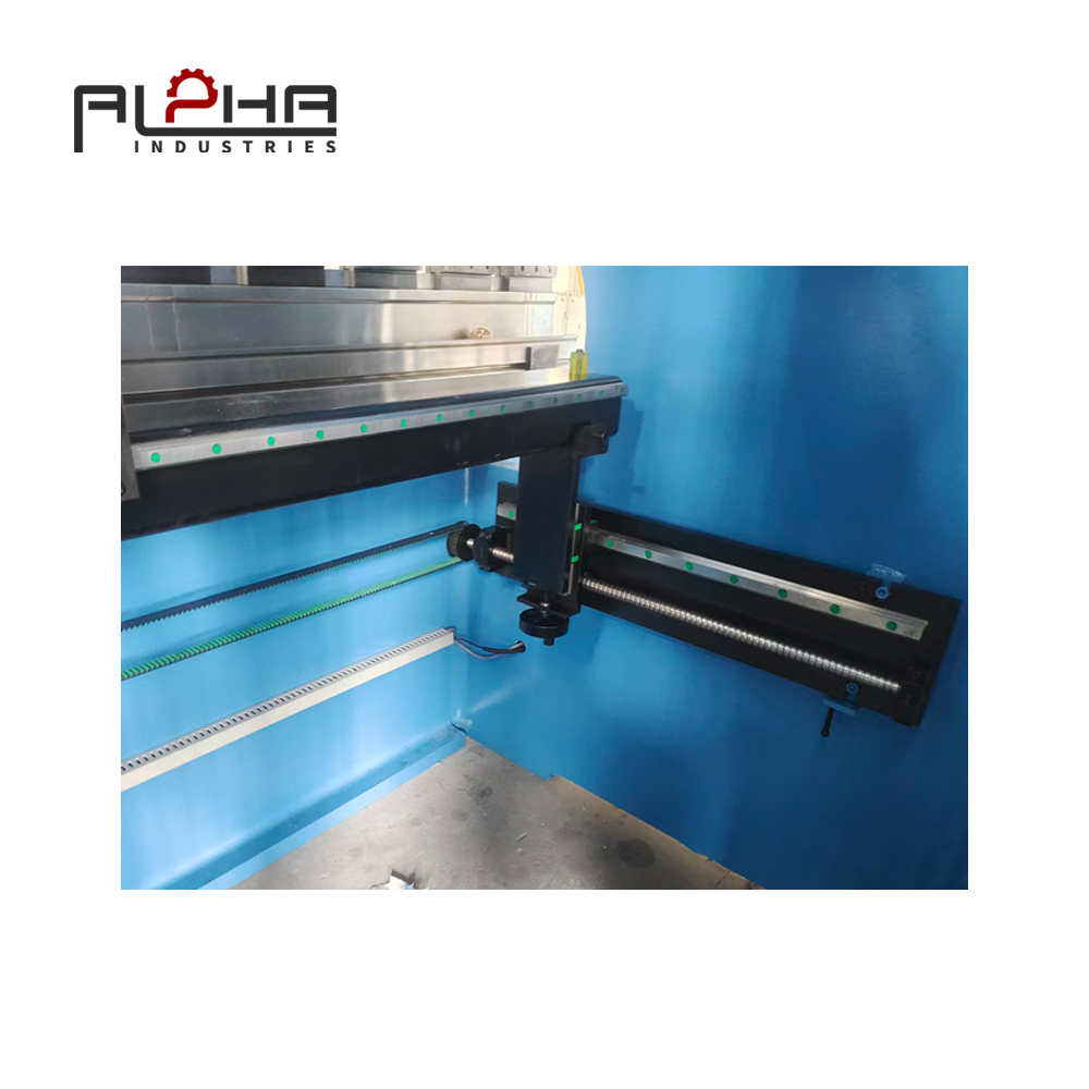
The machine's working length, throat depth, opening height, tooling arrangement, and available clearance should be appropriate for the intended applications.
Can the CNC System Support the Production Workflow?
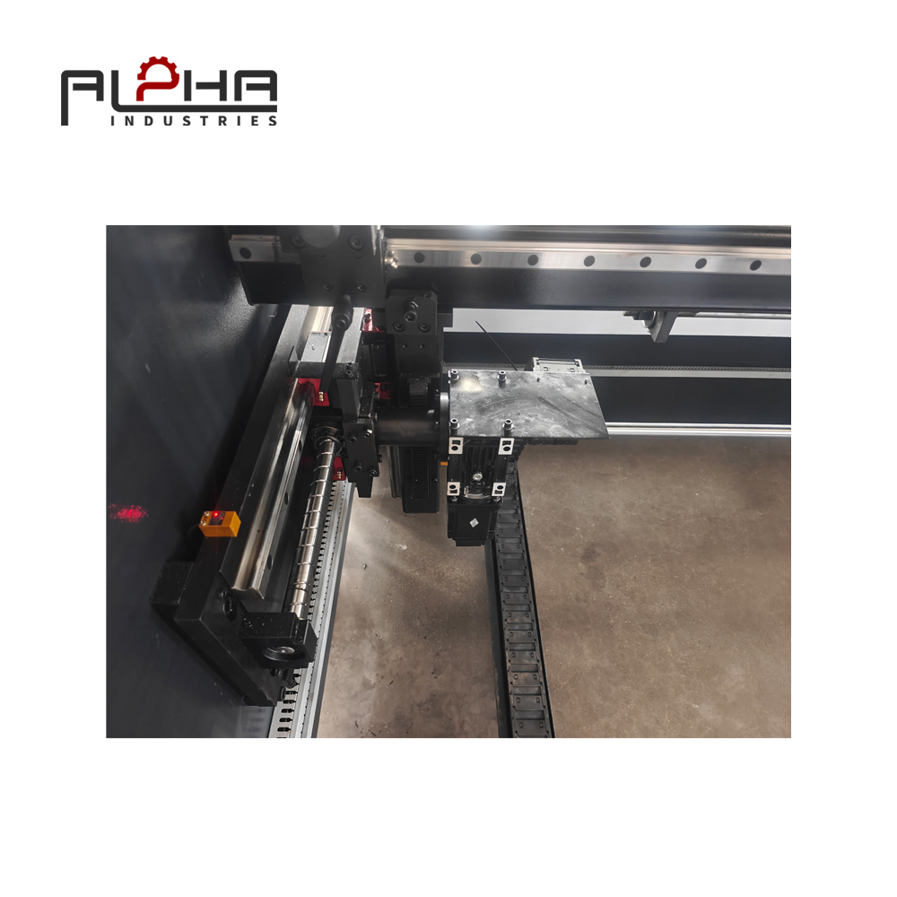
Consider the programming functions, stored programs, backgauge configuration, and other control features relevant to the parts being produced.
The exact capabilities vary by CNC system and machine configuration. Confirm the available functions with the supplier rather than assuming that every CNC press brake includes the same features.
Is the Tooling Compatible with the Required Bending Method?
Tooling geometry can affect the formed radius and the practical relationship between the flat pattern and the finished component.
Confirm that the proposed tooling can support the required material, thickness, bend geometry, and machine capacity.
Can the Supplier Review Representative Drawings?
Providing actual part drawings gives the supplier a clearer understanding of the intended application.
For complex components, a technical review can help identify questions about clearance, tooling, bending sequence, and machine configuration before the purchase is finalized.
What Technical Documentation Is Available?
Clarify which operating manuals, CNC documentation, maintenance information, and other technical materials are supplied with the machine.
For manufacturers that rely on repeat orders, consistent production documentation is an important part of long-term process control.
How ALPHA CNC Supports Press Brake Selection
For manufacturers in Ukraine, selecting a press brake should involve more than comparing bending force and machine price. The machine must be suitable for the material range, component geometry, tooling requirements, and production workflow.
ALPHA CNC provides metalworking machinery solutions for manufacturers evaluating their sheet metal processing requirements.
When discussing a CNC press brake application, relevant considerations include material type, sheet thickness, bending length, part geometry, CNC configuration, backgauge requirements, tooling compatibility, and required dimensional accuracy.
If a manufacturer produces components with multiple bends or close assembly tolerances, sharing representative drawings can help clarify the technical requirements of the application.
The purpose is to evaluate a machine configuration that supports the intended manufacturing process and provides a practical foundation for repeat production.
For businesses handling customized orders, engineering and production coordination should be considered alongside the machine itself. Accurate flat patterns, validated bending programs, and clear drawing revisions all contribute to a more controlled manufacturing workflow.
Frequently Asked Questions About Press Brake Bend Allowance
What is bend allowance in sheet metal bending?
Bend allowance is the length of material along the neutral axis within the bend region. It is used to calculate the developed flat length of a bent sheet metal component. The value depends on the bend angle, inside radius, material thickness, K-factor, and the calculation method used.
What is the difference between bend allowance and bend deduction?
Bend allowance represents the developed length of the curved bend region. Bend deduction is used with outside flange dimensions to calculate the flat length by subtracting the appropriate amount from the sum of those dimensions. The two values serve related purposes but should not be used interchangeably.
What is the K-factor in press brake bending?
The K-factor represents the position of the neutral axis relative to material thickness. It is used in bend allowance calculations to estimate the developed length of the bend. Its practical value depends on the material and forming conditions, so it should not automatically be treated as universal.
Can I use the same K-factor for all sheet metal materials?
Not reliably for every application. Different materials, thicknesses, bend radii, tooling configurations, and forming methods can produce different results. Use an appropriate initial value and validate the calculation against actual production conditions, especially for critical parts.
Why is my flat pattern correct in CAD but the finished part is too long or too short?
Possible causes include incorrect bend allowance or deduction settings, an unsuitable K-factor, a mismatch between the modeled and formed inside radius, material differences, tooling changes, or measurement issues. Check the calculation method and actual production conditions systematically before making corrections.
Does material thickness affect bend allowance?
Yes. Material thickness is one of the main inputs in bend allowance calculations. Changes in thickness can affect the developed length, and the resulting part may not meet its dimensions if the calculation uses an unsuitable thickness value.
Does changing the press brake tooling affect flat pattern accuracy?
It can. Different tooling and bending conditions may affect the resulting inside radius and formed geometry. When a tooling change is significant, verify whether the existing flat pattern assumptions remain valid and inspect a representative part when required.
How can manufacturers reduce flat pattern errors?
Use consistent calculation methods, controlled material-specific bend data, accurate drawing revisions, representative first-piece inspection, and clear communication between engineering and production. Record validated results so that repeat orders can use the correct approved process.
What should be checked during first-piece inspection?
Check the critical finished dimensions specified by the drawing. Depending on the component, these may include flange lengths, overall dimensions, bend angles, hole-to-bend distances, inside radius, and assembly interfaces. A correct bend angle alone does not guarantee that every dimension is acceptable.
Should a new material batch require a new flat pattern?
Not automatically. The need for recalculation or validation depends on the material specification, the differences between batches, the part's tolerance requirements, and the established process. If material properties or thickness differ meaningfully from the validated conditions, review whether the existing settings remain suitable.
Conclusion: Connect Engineering Calculations with Real Press Brake Production
Accurate flat pattern development is an essential part of successful sheet metal fabrication. Bend allowance, bend deduction, K-factor, material thickness, inside radius, tooling, and forming method all influence the relationship between a flat blank and its finished geometry.
For Ukrainian manufacturers handling customized orders and changing material requirements, errors in this relationship can lead to wasted material, repeated engineering work, dimensional problems, and assembly delays.
The most reliable approach is to standardize calculation methods, document material and process assumptions, maintain drawing revision control, and validate new or changed applications using representative parts.
A CNC press brake is one part of this system. Its configuration and tooling should support the intended geometry and production workflow, while engineering and production teams work from consistent, approved data.
By connecting CAD calculations with real manufacturing conditions, manufacturers can build a more repeatable process from the original design to the finished sheet metal component.
Contact ALPHA CNC
Are you planning to purchase a CNC press brake for your sheet metal manufacturing business in Ukraine? Share your material specifications, bending requirements, part drawings, and production goals with ALPHA CNC to discuss a suitable machine configuration.
Contact us: https://alpha-cnc.com/contact-us
Visit our website: https://alpha-cnc.com/