

Introduction: Why Press Brake Tooling Deserves More Attention
When manufacturers evaluate a press brake, they often focus on bending force, working length, CNC control, backgauge configuration, and machine price. These factors are important, but tooling deserves equal attention.
The punch and die directly influence how sheet metal is formed. Even a capable CNC press brake may struggle to produce consistent parts if the tooling is unsuitable for the material, thickness, bend geometry, or required surface finish.
For Ukrainian sheet metal manufacturers, tooling selection is particularly relevant when production involves different customer specifications, short production runs, changing material batches, and a broad range of components. A fabrication workshop may need to bend mild steel for structural parts, stainless steel for equipment housings, and aluminum for lightweight assemblies. Each application can place different demands on the tooling system.
Using one tooling configuration for every job may appear convenient, but it does not always provide the best balance of accuracy, surface quality, flexibility, and tool life.
The more effective approach is to treat tooling as part of the complete bending process. Material properties, sheet thickness, die opening, punch geometry, inside bend radius, machine capacity, and part design should be considered together.
For manufacturers in Ukraine, a well-planned tooling strategy can help make production more predictable while supporting different product specifications and customer requirements.
Why Tooling Selection Matters in the Ukrainian Market
Sheet metal manufacturers rarely work with only one material or one part design throughout the year. Orders may vary in quantity, dimensions, tolerances, and finish requirements. A tooling setup that performs well on one component may not be suitable for the next.
Several practical challenges make tooling selection important.
Different Materials Require Different Bending Approaches
Mild steel, stainless steel, and aluminum do not behave identically during bending. Their strength, ductility, surface sensitivity, and elastic recovery can differ significantly.
For example, stainless steel may require more forming force than mild steel of the same nominal thickness, depending on the grade and bending conditions. Its springback behavior may also require a different process setup.
Aluminum introduces different considerations. Some grades are more sensitive to cracking, particularly when the bend radius is too small or the material condition is unsuitable for the application. Surface protection may also be important when producing visible panels or finished components.
These differences mean that tooling should not be selected according to thickness alone. Material grade, mechanical properties, required bend radius, and surface finish must also be considered.
Customized Orders Increase Tooling Complexity
A manufacturer serving multiple industries may produce electrical cabinets, machine covers, equipment frames, brackets, panels, and structural components. These products can have very different flange lengths, bend angles, internal clearances, and dimensional requirements.
When orders change frequently, the tooling system must support a suitable range of applications without introducing unnecessary complexity.
The objective is not to purchase every available punch and die. It is to identify a practical tooling combination that covers the workshop's most common jobs while providing appropriate options for special components.
Surface Quality Can Affect the Finished Product
For some components, dimensional accuracy is not the only acceptance requirement. Scratches, dents, visible marks, and inconsistent bend lines can affect appearance and downstream finishing.
This is particularly important for exposed panels, stainless steel parts, coated materials, and components that will be painted or assembled into finished equipment.
The punch and die must therefore be compatible not only with the bending geometry but also with the required surface condition.
Understanding the Main Components of Press Brake Tooling
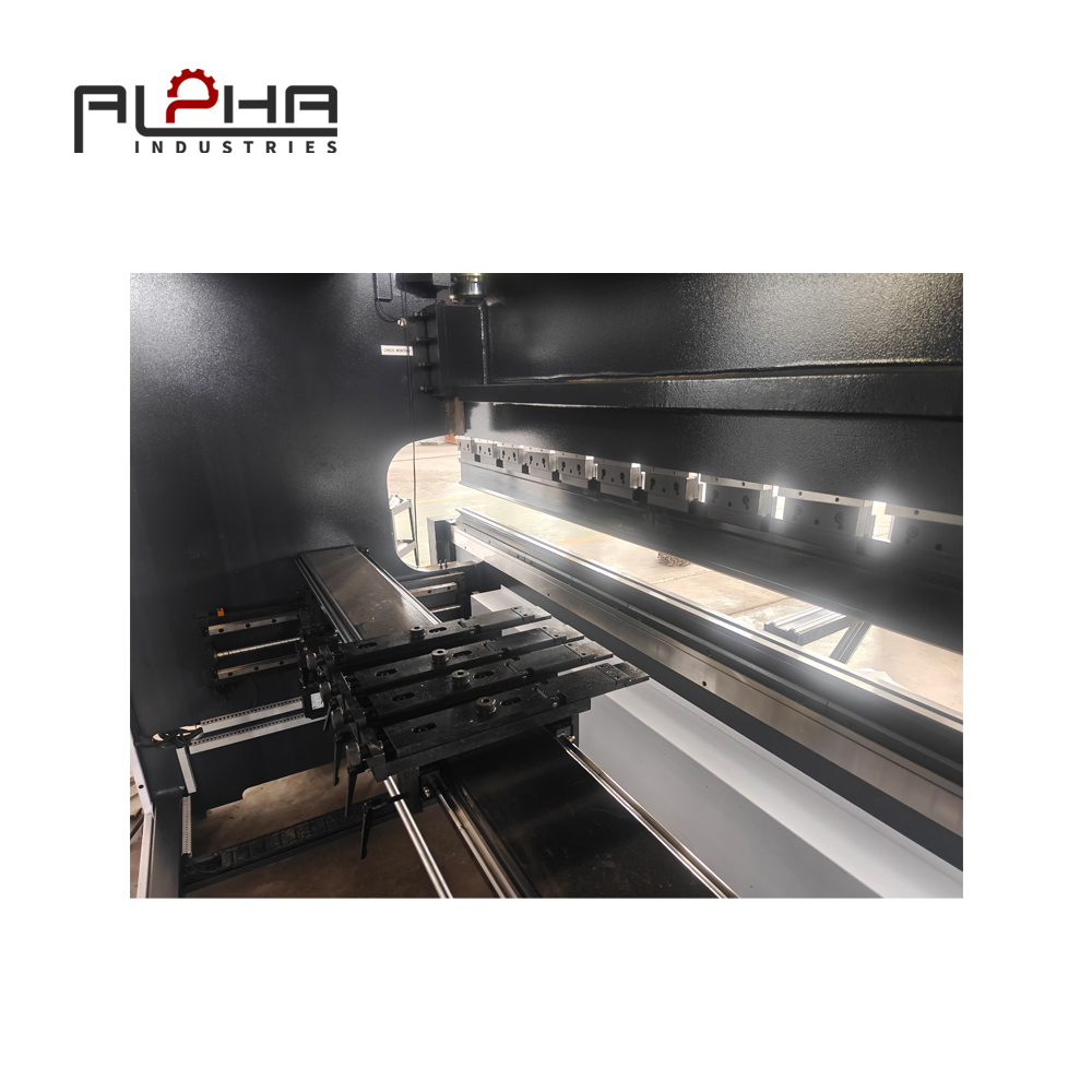
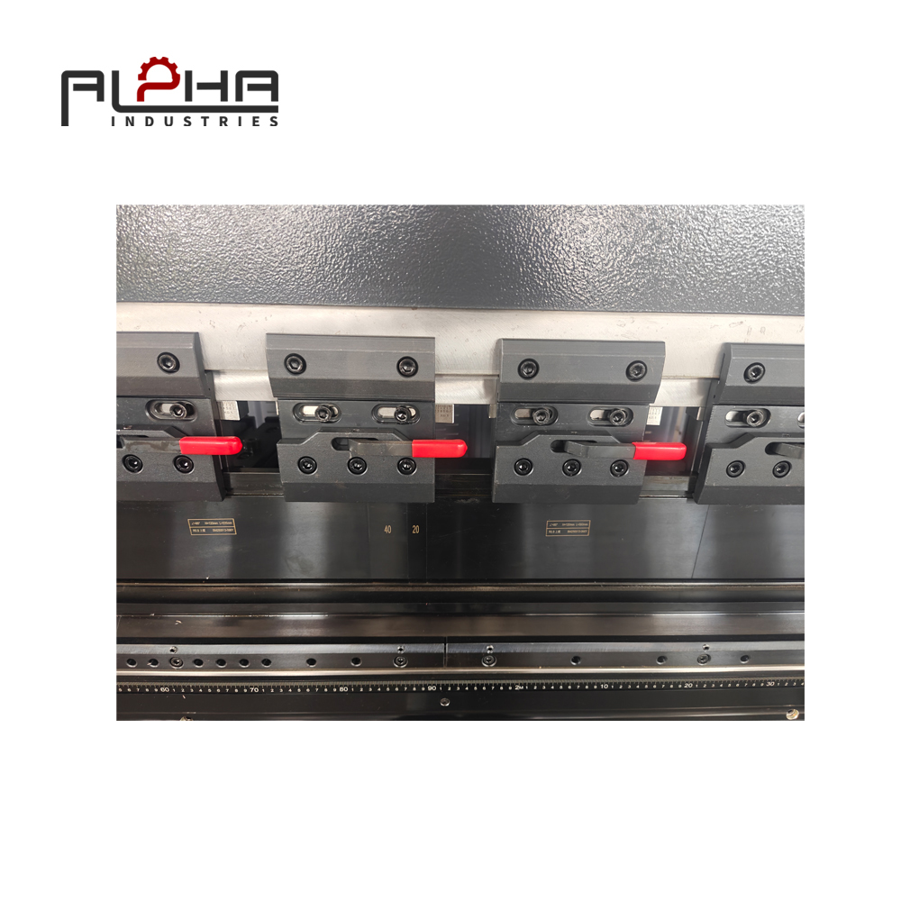
A conventional press brake tooling system consists primarily of an upper punch and a lower die.
The punch moves downward to form the sheet against the die. Their geometry determines how the material is supported and deformed during bending.
Press Brake Punches
The punch is the upper tool that applies force to the workpiece. Different punch profiles are designed for different bending applications.
Common punch considerations include:
-
Punch angle
-
Nose radius
-
Working height
-
Profile and clearance
-
Tool segment length
-
Load capacity
-
Compatibility with the machine's clamping system
A straight punch may suit many standard bending operations, while a gooseneck punch can provide clearance for certain return flanges and formed profiles. Other specialized punch designs may be required for particular part geometries.
However, no punch profile is universally suitable. The correct choice depends on the shape of the finished part, the required bend angle, the material, and the surrounding geometry.
Press Brake Dies
The lower die supports the workpiece during bending. In air bending, the V-die opening is one of the most influential tooling parameters.
A die with an unsuitable opening may produce a bend radius or forming result that does not meet the part specification. It can also affect the force required and the risk of damaging the material.
Die selection should consider:
-
V-opening
-
Die shoulder radius
-
Die angle
-
Die height
-
Load capacity
-
Workpiece support
-
Surface condition
-
Compatibility with the selected punch
Punch and die selection must be coordinated. Choosing the upper and lower tools independently can lead to clearance problems, unsuitable forming geometry, or an inability to complete the intended bend sequence.
How to Match V-Die Opening to Sheet Thickness
V-die opening is a central consideration in air bending. It affects the resulting inside bend radius, required bending force, and the relationship between the sheet and tooling.
A commonly used starting guideline for air bending mild steel is to select a V-opening of approximately six to eight times the material thickness. This is only a preliminary guideline, not a universal engineering rule.
The appropriate opening may differ according to material grade, tensile strength, bend radius requirements, sheet thickness, bending method, and the tooling manufacturer's recommendations.
For stainless steel, high-strength steel, aluminum, and other materials, the selection may need to be adjusted according to actual material behavior and the intended result.
What Happens When the V-Die Opening Is Too Small?
An excessively narrow die opening can increase the required forming force. Depending on the material and process, it may also produce a smaller inside radius than required or increase the risk of marking and material damage.
The machine and tooling capacity must be checked before using a narrow opening, particularly when working with thick or high-strength sheet metal.
What Happens When the V-Die Opening Is Too Large?
A wider V-opening generally produces a larger inside bend radius in air bending. It may also require less force than a narrower opening under otherwise comparable conditions.
However, a larger opening can be unsuitable when a part requires a small bend radius or a short flange. Workpiece support and dimensional requirements must also be considered.
The goal is not to choose the smallest or largest available die. It is to select an opening that supports the required geometry while remaining within the limits of the material, tooling, and press brake.
Why Trial Bending and Measurement Still Matter
Calculated tooling guidelines provide a useful starting point, but they cannot replace validation on the actual material.
Before releasing a new job into production, manufacturers should verify the finished bend angle, inside radius, flange dimensions, surface condition, and other drawing requirements.
If the result differs from the target, the cause should be identified before changing multiple process parameters at once. Tooling geometry, material properties, machine settings, and measurement methods can all influence the outcome.
Choosing Tooling for Mild Steel, Stainless Steel, and Aluminum
A practical tooling plan begins with the materials processed most frequently in the workshop.
Mild Steel
Mild steel is widely used for brackets, frames, covers, enclosures, and general fabrication. Tooling selection should reflect the material thickness, required inside radius, bend length, and dimensional tolerances.
For recurring mild-steel jobs, manufacturers may establish a set of validated punch-and-die combinations for common thickness ranges. This helps create a more standardized process without assuming that one die is appropriate for every application.
Stainless Steel
Stainless steel applications often require attention to both forming behavior and surface appearance.
The material's strength and springback characteristics can influence the bending setup. Contact between the sheet and tooling can also leave visible marks, depending on the material finish and process conditions.
Where appearance is important, manufacturers should evaluate suitable tooling surfaces, protective films or protective materials where appropriate, and process methods that reduce unwanted marking.
Tooling must still be capable of carrying the required load. Surface protection should never replace proper capacity checks or correct punch-and-die selection.
Aluminum
Aluminum includes different alloys and tempers with varying forming characteristics. A tooling configuration suitable for one aluminum grade may not be appropriate for another.
The required bend radius, material condition, grain direction, and risk of cracking should be reviewed before production. A radius that is too small for the selected material may compromise part quality.
For visible aluminum panels, surface protection and careful handling may also be important. Manufacturers should validate the complete process rather than relying on a generic tooling recommendation.
Protecting Surface Finish During Press Brake Bending
Surface marks are not always caused by a defective machine. They may result from the interaction between the workpiece, tooling geometry, contact pressure, and production conditions.
This issue is especially relevant when manufacturing visible stainless steel panels, coated sheets, decorative components, and finished enclosures.
Several measures can help protect surface quality.
Inspect Tooling Before Production
Punch and die surfaces should be checked for dirt, chips, damage, wear, and other conditions that may affect the workpiece.
Even small particles trapped between the sheet and tooling can leave marks. Routine inspection and cleaning are simple but important parts of process preparation.
Match Tooling to the Required Finish
Where surface appearance is critical, tooling selection should account for the material finish and the visibility of contact marks.
Depending on the application, suitable protective films, protective inserts, or specialized tooling surfaces may help reduce marking. Their suitability should be confirmed for the material, bending method, and required accuracy.
Avoid Unnecessary Tooling Changes
Frequent changes between unsuitable or poorly matched tools can introduce additional setup variation and increase the chance of using the wrong configuration.
A documented tooling plan helps operators identify the approved punch and die for each part family. It also makes it easier to reproduce a successful setup when a repeat order arrives.
Check the Finished Part, Not Just the Machine Movement
A smooth machine cycle does not automatically mean that the finished part meets specification.
Inspection should include visible surface areas, bend lines, edges, and other features defined by the drawing or customer quality requirements.
For critical components, manufacturers should define acceptance criteria before production begins.
Tooling Compatibility, Machine Capacity, and Safety
Tooling selection must always be checked against the press brake's operating limits.
The required bending force depends on several factors, including material type, thickness, bending length, die opening, and bending method. A tooling combination that works for a short workpiece may not be suitable for the same thickness across a much longer length.
Before production, manufacturers should verify the rated load of the punch and die, allowable load distribution, machine capacity, clamping compatibility, and the intended working length.
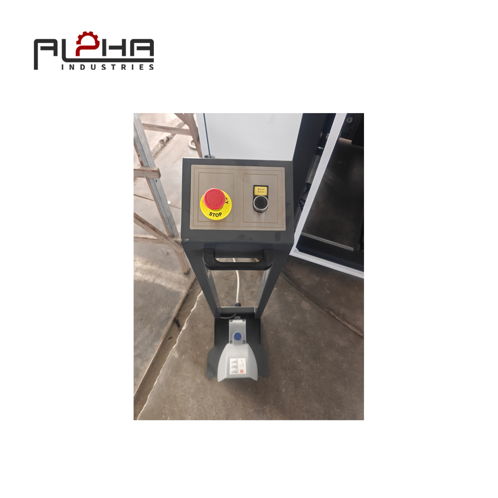
Tooling should also be installed and secured according to the machine and tooling manufacturer's instructions. Operators must follow the specified safety procedures and use the appropriate protective equipment and safeguards.
For Ukrainian manufacturers purchasing a new CNC press brake, the tooling system should be evaluated together with the machine rather than as a separate afterthought.
A suitable machine configuration should reflect actual production requirements, including material range, common thicknesses, part geometry, tooling availability, and future product plans.
Standardizing Tooling for Repeatable Production
A workshop can own a large collection of punches and dies and still experience inconsistent results if tooling selection depends entirely on individual operator experience.
A more structured approach is to establish a tooling reference for common part families.
Each record can include:
-
Part number or part family
-
Material grade
-
Nominal thickness
-
Required bend angle
-
Target inside bend radius
-
Selected punch
-
Selected die and V-opening
-
Tooling load limits
-
CNC program reference
-
Inspection requirements
-
Notes on surface protection
-
Approved process corrections, where applicable
The exact information required depends on production complexity and the capabilities of the CNC control system.
The purpose is to make proven setups easier to identify and reproduce. When the same component is ordered again, operators can refer to the validated process instead of rebuilding the tooling decision from memory.
This is useful for manufacturers managing several shifts, multiple operators, or a changing product mix.
Standardization also supports troubleshooting. If a bend result changes, the workshop can compare the actual setup with the approved tooling record and investigate the difference systematically.
How to Build a Practical Press Brake Tooling Inventory
An effective tooling inventory should reflect actual production rather than an arbitrary number of tools.
A useful starting point is to review recent orders and group components by material, thickness, bend geometry, and production frequency.
Identify the Most Common Jobs
List the material types and thickness ranges used most frequently. Include the required bend angles, inside radii, flange dimensions, and surface-finish expectations.
This review helps distinguish everyday tooling requirements from tools needed only for occasional special parts.
Prioritize Versatility and Compatibility
Select tooling that can support a useful range of applications without compromising required geometry or capacity.
Segmented tooling may provide flexibility for different workpiece lengths and configurations, depending on the tooling system. However, segment arrangement, alignment, load limits, and clamping requirements must be respected.
Keep Special Tooling for Defined Applications
Some parts require a specific punch profile, unusual clearance, or a particular die geometry. These tools should be identified by their intended application and stored so they can be selected correctly.
Special tooling should not be treated as interchangeable with standard tools unless the application and technical specifications confirm compatibility.
Review Tool Condition and Inventory Records
Tooling condition can change over time. Regular inspection helps identify wear or damage before it affects production.
Inventory records should also make it clear which tools are available, which are assigned to specific jobs, and which require inspection or replacement.
The goal is a tooling inventory that supports the workshop's actual product mix, not simply a large collection of tools.
Common Press Brake Tooling Mistakes to Avoid
Several avoidable mistakes can create bending problems even when the press brake itself is capable of meeting the required specification.
-
Selecting a die based on thickness alone. Material strength, bend radius, part geometry, and bending method also matter.
-
Ignoring the required inside radius. The selected tooling must support the geometry specified by the design, subject to the material's forming limitations.
-
Using unsuitable tooling for visible surfaces. Surface-sensitive applications may need additional attention to tool condition, protective methods, and contact marking.
-
Overlooking tool load limits. Punches and dies must be suitable for the actual load and its distribution along the working length.
-
Assuming all materials behave the same way. Different alloys, grades, and material batches can produce different results under similar nominal settings.
-
Changing several parameters without identifying the cause. Uncontrolled adjustments make it difficult to understand which change improved or worsened the result.
-
Failing to document successful setups. Without records, repeat orders may require unnecessary trial bending and repeated process validation.
A controlled tooling selection process helps manufacturers identify these issues before they become recurring production problems.
What Should Ukrainian Manufacturers Ask Before Buying a CNC Press Brake?
Tooling compatibility should be included in the purchasing discussion, particularly when the machine will process a wide range of parts.
Before choosing a CNC press brake, manufacturers should clarify the following questions.
Which materials and thicknesses will the machine process most often?
The answer helps define the required bending force, tooling range, and suitable machine configuration.
What bend lengths and part geometries are common?
Long panels, short flanges, return bends, and complex profiles can require different tooling considerations and clearances.
What inside bend radii and surface finishes are required?
These requirements influence punch geometry, die selection, and the need for surface-protection measures.
Which tooling standards and clamping systems are compatible?
Tooling compatibility affects setup planning, the use of existing tools, and future tooling purchases. The exact interface and specifications should be confirmed before ordering.
What is included in the proposed machine configuration?
Manufacturers should clarify which punches, dies, clamping components, and optional features are included and which must be purchased separately.
How will tooling be maintained and replaced?
Tool availability, inspection procedures, storage, and replacement planning all affect the long-term usability of the bending system.
Can the supplier assess a representative workpiece?
Providing drawings, material specifications, thickness ranges, and sample-part requirements helps the supplier assess the application more accurately.
These questions help ensure that the selected press brake is suitable for the actual production environment rather than only meeting a nominal tonnage or working-length requirement.
How ALPHA CNC Supports Press Brake Selection
For Ukrainian manufacturers, selecting a press brake should begin with a clear understanding of the parts to be produced and the quality standards they must meet.
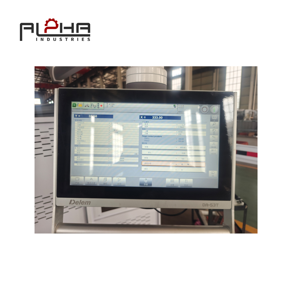
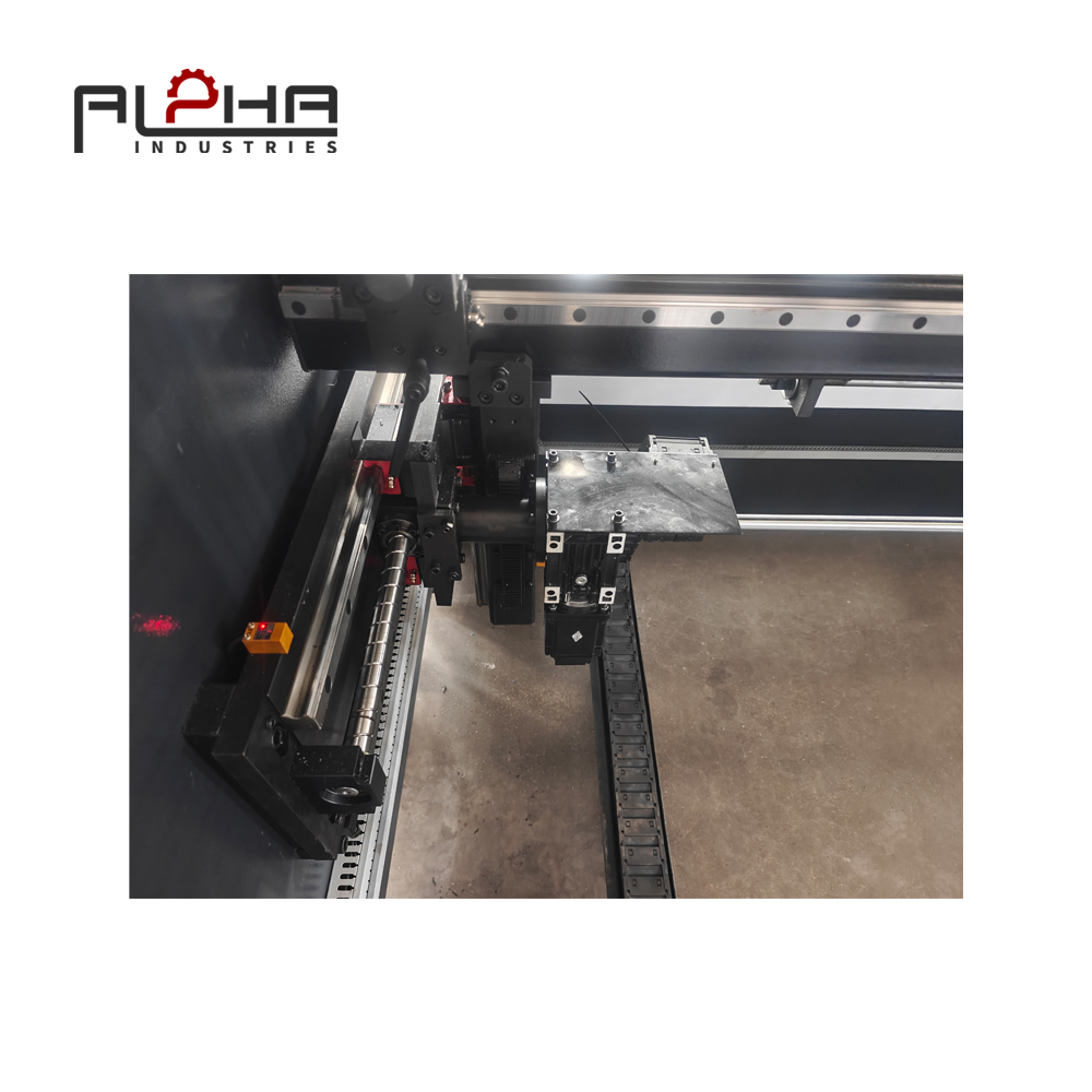
ALPHA CNC offers metalworking machinery solutions for manufacturers evaluating their sheet metal processing requirements. When considering a press brake, the important factors include bending force, working length, material range, CNC control, backgauge configuration, tooling compatibility, and the dimensional and surface-finish requirements of the finished parts.
The appropriate solution depends on the application. A workshop producing standard mild-steel brackets may have different tooling needs from a manufacturer producing visible stainless steel panels or complex custom components.
Preparing representative drawings and material specifications can help clarify the required machine and tooling configuration before purchase.
Rather than evaluating a press brake only by its maximum capacity, manufacturers should consider whether the complete system can support their recurring jobs, special applications, and future production plans.
For businesses in Ukraine facing changing order requirements and pressure to maintain consistent product quality, a well-matched machine and tooling package can provide a more practical foundation for reliable bending operations.
Frequently Asked Questions About Press Brake Tooling
How do I choose the right press brake punch and die?
Start with the material grade, thickness, required inside bend radius, bend angle, workpiece geometry, and surface-finish requirements. Then check the punch and die dimensions, load ratings, machine compatibility, and the intended bending method. Validate the setup on the actual material before releasing the part for production.
How do I choose a V-die opening for sheet metal bending?
For air bending mild steel, a V-opening of approximately six to eight times the material thickness is often used as an initial guideline. The appropriate opening depends on the material, thickness, bend radius, required geometry, tooling specifications, and machine capacity. Treat the guideline as a starting point rather than a universal rule.
Can one press brake die be used for different materials?
Sometimes, but not every die is suitable for every material and thickness. Different materials have different forming characteristics, and the same die opening may produce different radii or bending results. Verify the application, tooling capacity, and finished-part requirements before reusing a tooling setup.
How can I reduce scratches during press brake bending?
Inspect and clean the tooling, select tools suitable for the material and required finish, and consider appropriate protective methods for surface-sensitive parts. Also check the workpiece for contamination and define clear surface-quality acceptance criteria. The best method depends on the material, tooling, and production application.
Why does the same tooling produce different bend results?
Possible causes include differences in material thickness or strength, tooling wear, changes in setup, incorrect positioning, machine calibration, and variation in measurement. Compare the actual conditions with the approved process and identify the source of the variation before making adjustments.
Does a CNC press brake require special tooling?
Not necessarily. A CNC press brake can use compatible standard tooling or specialized tooling, depending on the machine's clamping system and the part requirements. Tooling compatibility must be confirmed for the specific machine configuration. CNC control does not remove the need to select suitable punches and dies.
What should I consider when buying press brake tooling for a new machine?
Consider the material and thickness range, bend geometry, required inside radius, surface-finish requirements, tooling load capacity, clamping interface, tool availability, and the range of parts produced regularly. Confirm which tools are included with the machine and which need to be purchased separately.
How often should press brake tooling be inspected?
Tooling should be inspected according to its usage, condition, manufacturer recommendations, and the criticality of the parts being produced. Check for wear, damage, contamination, and other conditions that could affect safety or part quality. Any tooling suspected of being unsafe or outside its specifications should be removed from service until assessed.
Conclusion: Build a Better Bending Process from the Tooling Up
Press brake performance depends on more than machine tonnage and CNC capability. The punch and die determine how the material is supported and formed, making tooling selection a central part of bending quality.
For Ukrainian sheet metal manufacturers, a structured tooling strategy can help address the practical challenges of processing different materials, handling customized orders, protecting visible surfaces, and maintaining repeatable dimensions.
The most reliable approach is to match tooling to the material and part geometry, verify load and machine compatibility, inspect tools regularly, and document successful setups for repeat production.
A carefully selected tooling system will not eliminate every forming challenge, but it can help manufacturers make better-informed process decisions and build a more consistent production workflow.
When evaluating a new CNC press brake, consider the complete bending application: the machine, the tooling, the material, the part design, and the inspection process. This provides a stronger basis for choosing equipment that meets real production requirements.
Contact ALPHA CNC
Are you looking for a CNC press brake for your sheet metal manufacturing business in Ukraine? Share your material specifications, sheet thicknesses, bending length, part drawings, and production requirements with ALPHA CNC to discuss a suitable machine configuration.
Contact us: https://alpha-cnc.com/contact-us
Explore our website: https://alpha-cnc.com/